
Wavelength division multiplexing optical transmission system

a transmission system and wavelength technology, applied in multiplex communication, instruments, optical elements, etc., can solve the problems of limiting affecting system performance, and affecting the transmission distance of the wavelength path

Inactive Publication Date: 2006-02-23
FUJITSU LTD
View PDF7 Cites 8 Cited by
  • Summary
  • Abstract
  • Description
  • Claims
  • Application Information

AI Technical Summary

Benefits of technology

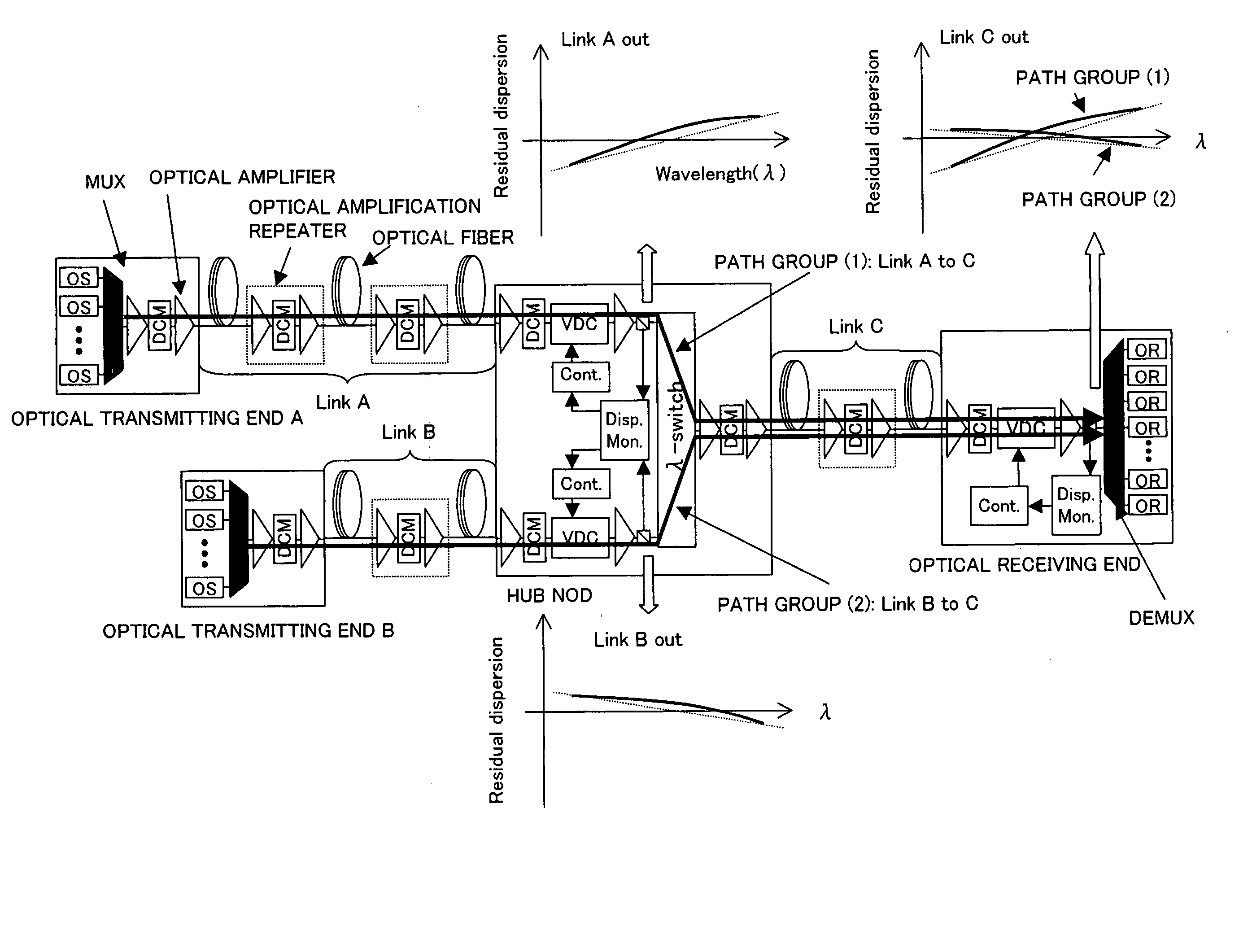
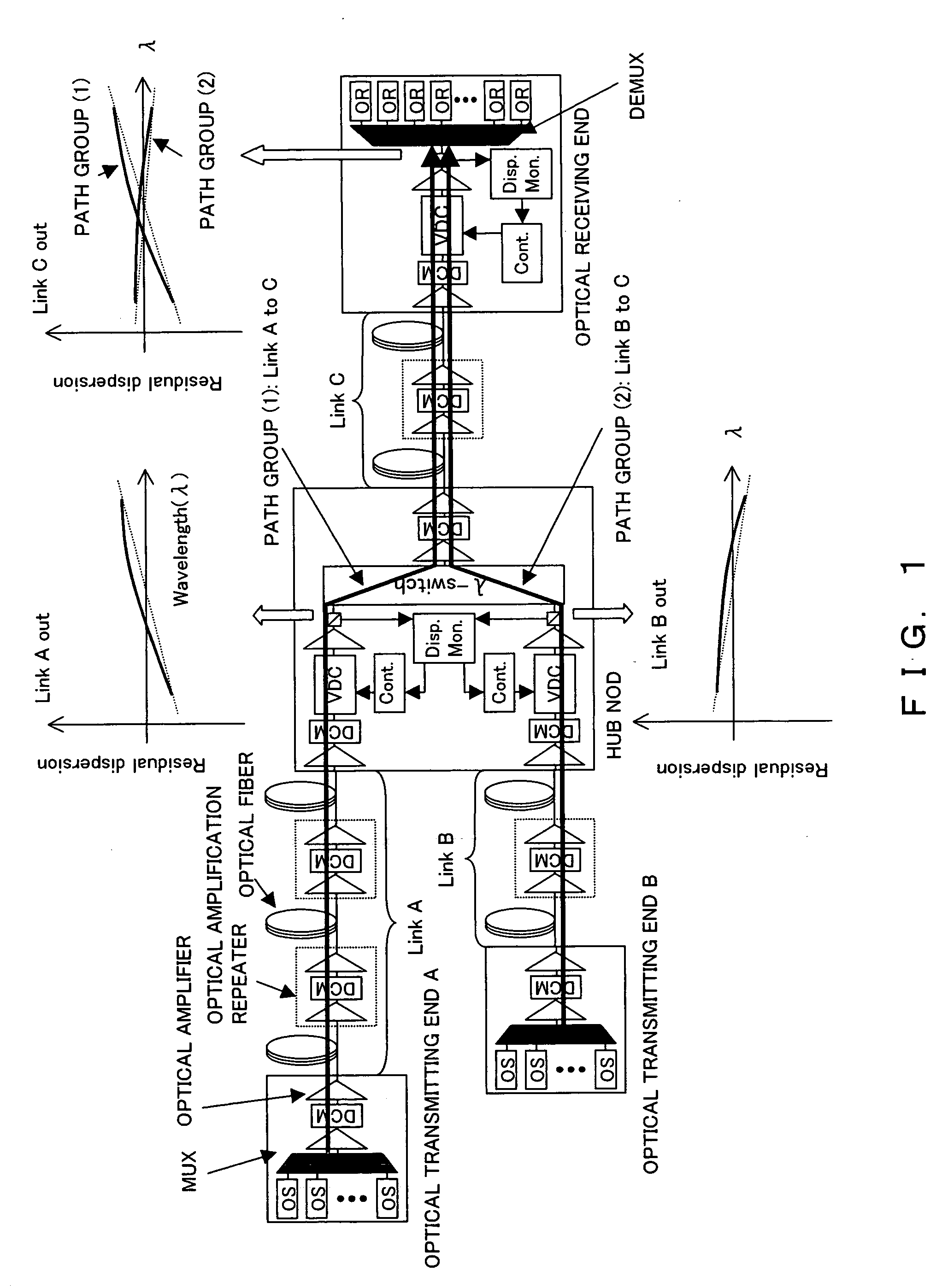
[0022] A plurality of variable chromatic dispersion compensators arbitrarily disposed in the photonic network is controlled based on the wavelength path information held by a network management system (NMS) which manages the entire photonic network and the measured results of a plurality of the chromatic dispersion monitors arbitrarily disposed in the photonic network. Based on the measured results of the chromatic dispersion monitor and the wavelength path information held by NMS, the variable chromatic dispersion compensators which should be controlled in the network are determined, as is its chromatic dispersion compensated quantity, thereby enabling the provision of a photonic network which has a transmission path on which the chromatic dispersion compensation is performed and which does not depend on the wavelength path.

Problems solved by technology

Furthermore, due to the difference in the accumulated chromatic dispersion characteristics of each wavelength path, the distortions of transmitted waveforms differ with each wavelength path, and this waveform distortion significantly limits the transmission distance of the wavelength path.
Therefore, since the accumulated chromatic dispersion characteristics may differ with wavelength path, there arises a problem in that the transmission characteristics differ with wavelength path attributable thereto.
This causes the transmission distance to differ with wavelength path and becomes a factor in the deterioration of system performance.

Method used


Image

  • Wavelength division multiplexing optical transmission system
  • Wavelength division multiplexing optical transmission system
  • Wavelength division multiplexing optical transmission system

Examples


Embodiment Construction

[0045] Hereinafter, described are the chromatic dispersion compensation units to which the present invention is applied and the embodiments of the monitoring control units thereof.

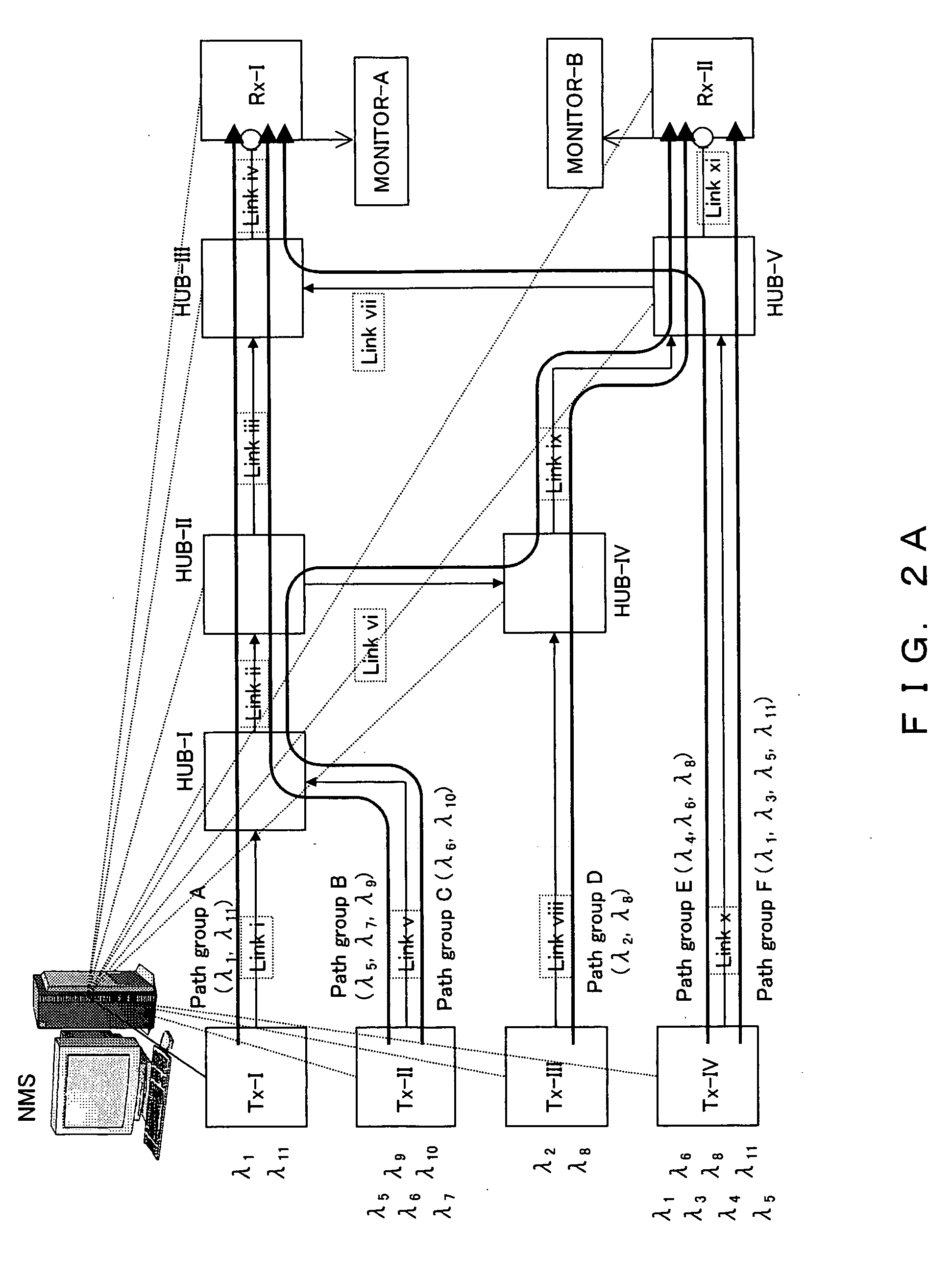
[0046]FIG. 2A is a diagram showing one example of the photonic network to which the present invention is applied.

[0047] The photonic network shown in FIG. 2A comprises the optical transmitting end (Tx-I to Tx-IV in the figure), the HUB node (HUB-I to HUB-V in the figure), the optical receiving end (Rx-I, Rx-II in the figure), the transmission paths (Link, Link i to Link xi in the figure), and the network management system (NMS in the figure) which is connected with each optical transmitting end, the HUB node, the optical receiving end and manages the entire network.

[0048] In addition, each transmission path (Link) comprises the cascade connection of the optical amplification repeaters and the optical fibers. The optical amplification repeater is configured to be connected to single or multistage optical...


PUM


Abstract

The objective of the present invention is to realize a chromatic dispersion compensation method which does not depend on a wavelength path in a photonic network to which a HUB node is applied and its monitoring control. In order to achieve this purpose, the present invention controls a plurality of variable chromatic dispersion compensators arbitrarily disposed in the photonic network based on the measured results of a plurality of chromatic dispersion monitors arbitrarily disposed in the photonic network and wavelength path information kept by the network management system which manages the entire photonic network. Here, the variable chromatic dispersion compensator within the network that should be controlled and the chromatic dispersion compensated quantity thereof are determined based on the measured results of the chromatic dispersion monitor and the wavelength path information kept by NMS.

Description

BACKGROUND OF THE INVENTION [0001] 1. Field of the Invention [0002] The present invention relates to a wavelength division multiplexing optical transmission system wherein chromatic dispersion compensation and monitoring control thereof are executed in a photonic network having a node device which performs an optically branched insertion and an optical path shifting of an optical signal as is. [0003] 2. Description of the Related Art [0004] Conventionally, construction of a photonic network having topology such as a ring and a mesh which utilize an OADM (Optical Add / Drop Multiplexing) node for performing the optically branched insertion of an optical signal as is, without performing photoelectric conversion, and a HUB node for performing the optical path shifting in wavelength unit (including drop and continue) is required. Realization of flexible and simple. operation and maintenance is expected in a photonic network such as this. [0005] The optical wavelength of each signal is reg...

Claims


Application Information

Patent Timeline
IPC IPC(8): H04B10/12H04B10/07H04B10/2507H04B10/2525H04B10/27H04B10/291H04J14/00H04J14/02
CPCH04B10/25133
Inventor KATAGIRI, TORUNAITO, TAKAO
Owner FUJITSU LTD
Learn More