Fluid-working machine and operating method

Inactive Publication Date: 2006-02-23
ARTEMIS INTELLIGENT POWER
View PDF9 Cites 55 Cited by
  • Summary
  • Abstract
  • Description
  • Claims
  • Application Information

AI Technical Summary

Benefits of technology

[0019] Preferably, the working chambers comprise cylinders in which pistons are arranged to reciprocate. If so, the partial pumping mode preferably includes closing the valve linking the cylinder to the low-pressure manifold and opening the valve linking the cylinder to the high-pressure manifold a small fraction in advance of the top dead centre position of the piston. The partial motoring mode preferably includes closing the valve linking the cylinder to the high-pressure manifold and opening the valve linking the cylinder to the low-pressure manifold a small fraction after the top dead centre position of the piston.
[0020] If valve actuations are delayed in this way to almost the end of the stroke, then the rate of change of chamber volume will be at an acceptably low level to permit valve actuation. This means that a small fraction of a whole cylinder can also be selected by the controller to add to the machine's output. The range over which this is practicable is limited by stability of valve ope

Problems solved by technology

Experience shows that varying the timing of the valves, such that portions of the stroke are disabled, in order to vary machine output creates a significant amount of audible and fluid borne noise.
It was considered that delayed closure of valves, occurring during times of significant flow, such that part of the chamber displacement could be rejected, would result in extremely high rates of change of flow and pressure, which in turn would generate noise.
However, in practice it was found that whole chamber selection during times of low flow demand resulted in large flow variations, seeing as the fluid machine was idle for long instances between active chambers.

Method used


Image

  • Fluid-working machine and operating method
  • Fluid-working machine and operating method
  • Fluid-working machine and operating method

Examples


Embodiment Construction

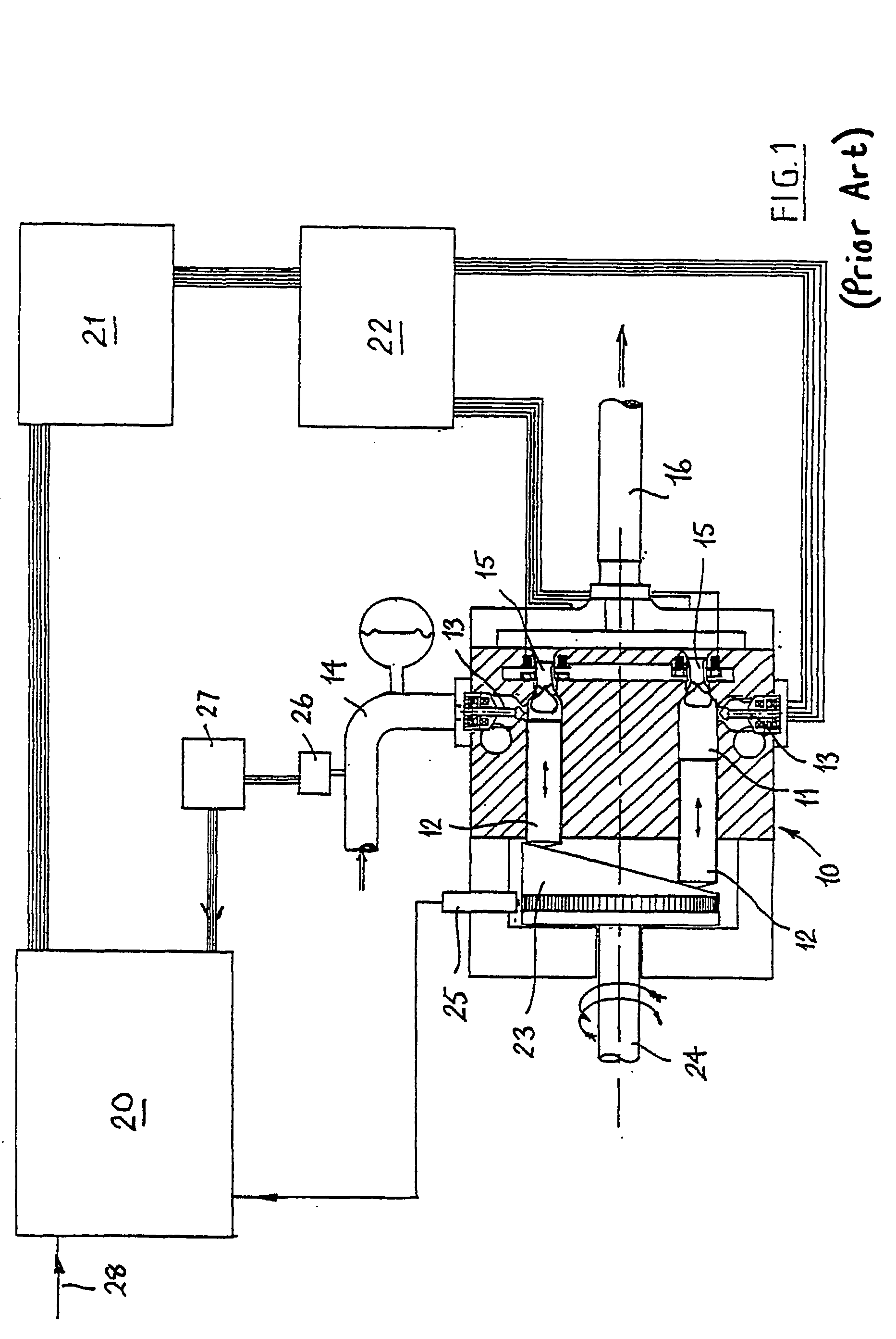
[0029] The machine described in EP-A-0494236 and shown in FIG. 1 can be adapted to provide a machine according to the invention without additional hardware to create a part-stroke mode. The adaptation consists of increasing the functionality and complexity of the microprocessor control algorithms.

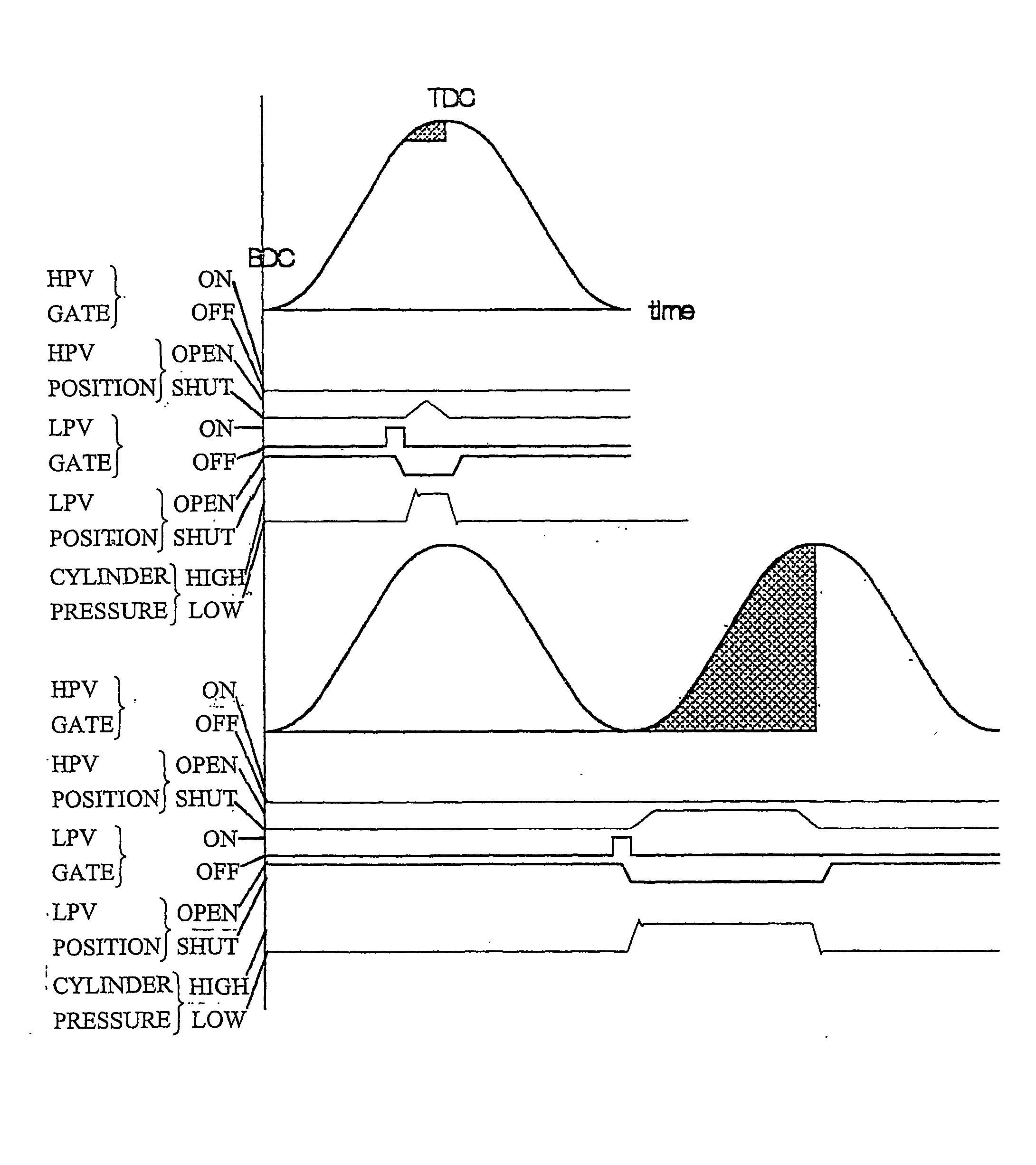
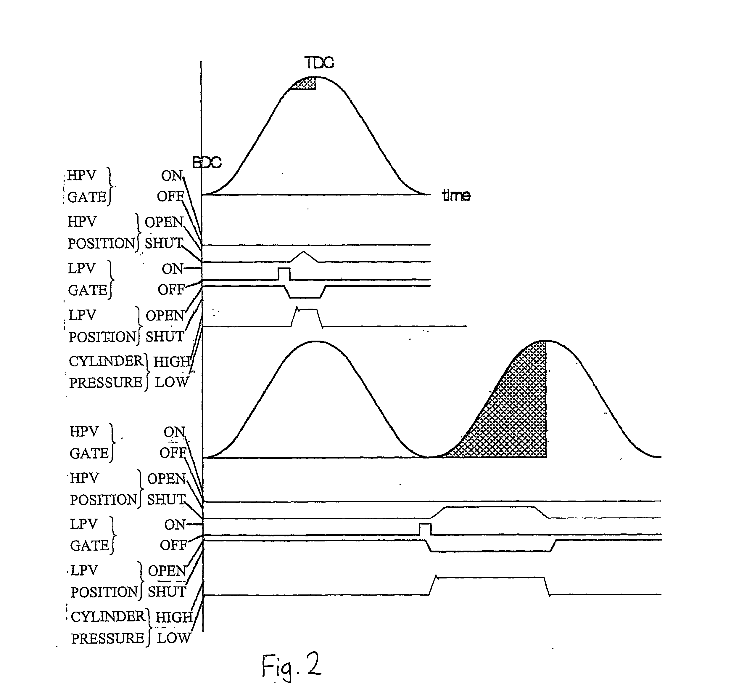
[0030] At any one instant there are four possible states for any of the chambers 11: (1) intake from the low-pressure manifold, (2) exhaust to the low-pressure manifold, (3) intake from the high-pressure manifold and (4) exhaust to the high-pressure manifold.

[0031] Let “mode” denote a repeating cyclic sequence of transitions from one of these states to another. There are five distinct modes: full stroke pumping, part stroke pumping, full stroke motoring, part stroke motoring, and idling.

[0032] The difference between full and part stroking modes is the phase angle at which transitions are made from one of these states to the other relative to bottom and top dead centre of piston movement:...


PUM


Abstract

A fluid-working machine has a plurality of working chambers, e.g. cylinders (11), of cyclically changing volume, a high-pressure fluid manifold (14) and a low-pressure fluid manifold (16), at least one valve (13, 15) linking each working chamber to each manifold, and electronic sequencing means (20) for operating said valves in timed relationship with the changing volume of each chamber (11), wherein the electronic sequencing means is arranged to operate the valves of each chamber in one of an idling mode, a partial mode in which only part of the usable volume of the chamber is used, and a full mode in which all of the usable volume of the chamber (11) is used, and the electronic sequencing means (20) is arranged to select the mode of each chamber on successive cycles so as to infinitely vary the time averaged effective flow rate of fluid through the machine.

Description

BACKGROUND TO THE INVENTION [0001] This invention relates to a fluid-driven (motor) and / or fluid-driving (pump) machine having a plurality of working chambers of cyclically changing volume and valve means to control the connection of each chamber to low- and high-pressure manifolds. The invention also relates to a method of operating the machine. [0002] The invention has particular reference to non-compressible fluids, but its use with gases is not ruled out. It has particular reference to machines where the at least one working chamber comprises a cylinder in which a piston is arranged to reciprocate, but its use with at least one chamber delimited by a flexible diaphragm or a rotary piston is not ruled out. [0003] With most fluid working machines the fluid chambers undergo cyclical variations in volume following a sinusoidal function. It is known to provide flow rectifying seating valves, allowing fluid to be admitted and exhausted from the working chamber, which valves are electr...

Claims


Application Information

Patent Timeline
IPC IPC(8): F04B49/00F04B27/08F04B7/00F04B49/06F04B49/22F04B49/24F04B53/10
CPCF04B7/0076F04B49/065F04B49/225F04B2201/0807F04B53/1082F04B2201/02F04B49/243F01B25/10F04B49/12
Inventor STEIN, UWE BERNHARDCALDWELL, NIALL JAMESRAMPEN, WILLIAM HUGHALMOND, JONATHAN PAUL
Owner ARTEMIS INTELLIGENT POWER
Why Eureka
Try Eureka