
Microfluidic device, and diagnostic and analytical apparatus using the same

a microfluidic device and diagnostic and analytical technology, applied in the direction of instruments, separation processes, laboratory glassware, etc., can solve the problems of requiring additional devices or operations, little research into such microchannels, etc., and achieve the effect of convenient use and easy manufactur

Inactive Publication Date: 2006-02-23
LG LIFE SCI
View PDF6 Cites 18 Cited by
  • Summary
  • Abstract
  • Description
  • Claims
  • Application Information

AI Technical Summary

Benefits of technology

[0010] The present invention provides a microfluidic device in which the flow of a very small volume of fluid can be quantitatively regulated through a channel having a particular design that can induce spontaneous flow by capillary force without additional manipulation processes and energy requirement. The microfluidic device can be easily manufactured and can be easily used. The present invention also provides a diagnostic and analytical apparatus using the microfluidic device.
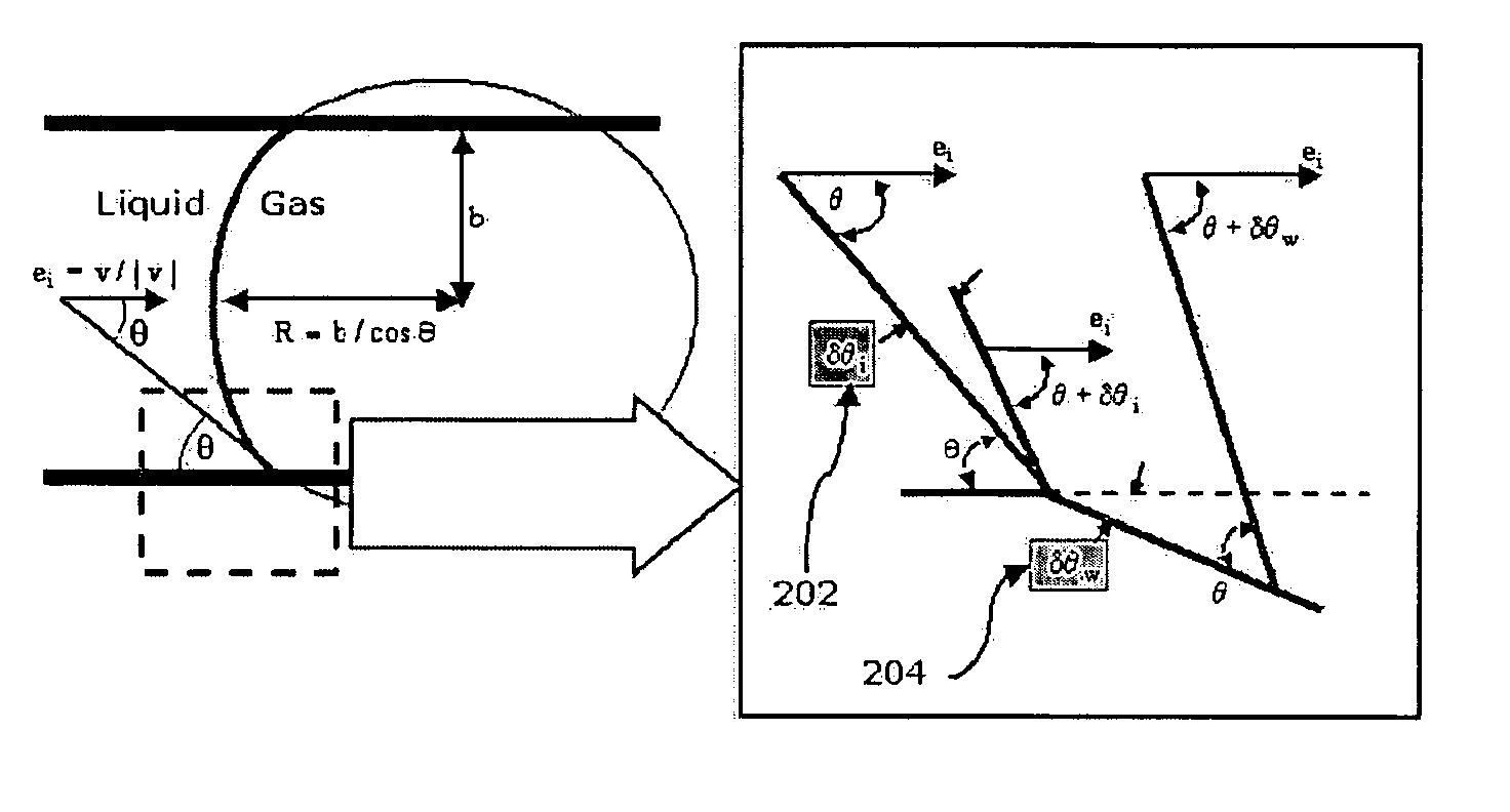
[0011] According to an aspect of the present invention, there is provided a microfluidic device having a microchannel through which a microfluid flows, the device comprising: an inlet portion through which the microfluid flows and which has a first cross-section and a predetermined length; a flow delaying portion which is located adjacent to the inlet portion to allow the microfluid from the inlet portion to enter, has a second cross-section that is larger than the first cross-section of the inlet portion to reduce the interfacial curvature of the microfluid entering from the inlet portion by capillary force and the flow rate of the microfluid, and has a predetermined length extending in a direction in which the microfluid flows; and a flow recovery portion which is located adjacent to the flow delaying portion to allow the microfluid from the flow delaying portion to enter, and has a third cross-section that is smaller than the second cross-section of the flow delaying portion and a predetermined length.
[0020] A front end of the acceleration wall near the cross-section enlarging portion may be shaped such that the microfluid incoming from the cross-section enlarging portion can easily branch off to flow into the plurality of acceleration channels.
[0029] At least one acceleration wall may be installed lengthwise in the main channel to increase the capillary force of the microfluid flowing along the main channel such that the microfluid can almost simultaneously reach the individual microfluidic channels.

Problems solved by technology

However, in such conventional microfluidic devices and diagnostic and analytical apparatuses using the same, despite the need for designing microchannels that can reduce the total time of analysis and in which the flow rate can be reduced in a section where reactions take place at a particular point in time to allow the sample sufficient reaction time and can be increased at a particular point in time to wash away the reaction product for identification, little research into such microchannels has been conducted.
However, this method requires an additional device or operation.

Method used


Image

  • Microfluidic device, and diagnostic and analytical apparatus using the same
  • Microfluidic device, and diagnostic and analytical apparatus using the same
  • Microfluidic device, and diagnostic and analytical apparatus using the same

Examples


first embodiment

[0081]FIG. 9A is a schematic view of a microfluidic device using a flow acceleration model according to the present invention. Referring to FIG. 9A, a microfluidic device 20 using a flow acceleration model according to the present invention includes an inflow portion 21 through which a microfluid flows and which has a first cross-section, a cross-section enlarging portion 22 into which the microfluid from the inflow portion 21 flows and which has cross-sections varying from the first cross-section to a second cross-section, which is larger than the first cross-section, and a predetermined length, and a flow accelerating portion 23 having substantially the same cross-section as the second cross-section and including at least one acceleration wall 24 arranged at intervals in the widthwise direction and extending along the lengthwise direction in which the microfluid flows, forming a plurality of acceleration channels 26.

[0082] To allow the microfluid flowing through the cross-section ...

second embodiment

[0089]FIG. 11 is a schematic view of a diagnostic and analytical apparatus according to the present invention, which includes a flow branch model using flow delaying models according to the present invention. Referring to FIG. 11, a diagnostic and analytical apparatus 1a including a plurality of microfluidic devices with microchannels through which a microfluid flows includes a main channel 30 along which the microfluid flows and a plurality of branch control units 40, which are connected to the main channel 30 and branch off the microfluid from the main channel 40 to flow into the plurality of microfluidic devices. Each of the branch control units 40 includes: a sub-channel 41, which is connected to the main channel 30 and has a first cross-section that is smaller than the cross-section of the main channel 30; a flow delaying portion 42, which is connected to the sub-channel 41, has a second cross-section that is larger than the first cross-section of the sub-channel 41 to reduce t...


PUM


Abstract

A diagnostic and analytical apparatus including the microfluidic device having: an inlet portion with a first cross-section, a flow delaying portion with a second cross-section that is larger than the cross-section of the inlet portion thereby reducing the interfacial curvature of the microfluid entering from the inlet portion by capillary force and the flow rate of the microfluid, and a flow recovery portion having a third cross-section that is smaller than the cross-section of the flow delaying portion. The flow of a very small volume of fluid can be quantitatively regulated through a channel having a particular design that can induce spontaneous flow by capillary force without additional manipulation processes and energy requirement.

Description

CROSS-REFERENCE TO RELATED PATENT APPLICATION [0001] This application claims the benefit of Korean Patent Application Nos. 10-2004-0066166, and 10-2004-0066171, both filed on Aug. 21, 2004, in the Korean Intellectual Property Office, the disclosures of which are incorporated herein in their entirety by reference. BACKGROUND OF THE INVENTION [0002] 1. Field of the Invention [0003] The present invention relates to a microfluidic device and a diagnostic and analytical apparatus using the same, and more particularly, to a microfluidic device which can quantitatively regulate a very small volume of fluid in capillary flow and a diagnostic and analytical apparatus using the same. [0004] 2. Description of the Related Art [0005] Microfluidic technologies for inducing and controlling the flow of very small volumes of fluid are essential to the driving of diagnostic and analytical apparatuses. Such technologies can be implemented using various driving methods. Typical driving methods include ...

Claims


Application Information

Patent Timeline
IPC IPC(8): G01N27/26
CPCB01L3/502746B01L2400/086B01L2400/0406B01L2300/0816
Inventor SUK, JI WONKIM, JAE KWONJEONG, JA HOONHAN, SANG PHILIM, YEHOONKIM, YOUNGDUK
Owner LG LIFE SCI
Learn More