Method for operating a radio system, emitting station and radio system

Inactive Publication Date: 2006-02-23
SIEMENS AG
View PDF19 Cites 49 Cited by
  • Summary
  • Abstract
  • Description
  • Claims
  • Application Information

AI Technical Summary

Benefits of technology

[0024] In a further advantageous embodiment of the invention the direction information specifies the geographical position of the emitting station in each case and the relevant spatial direction in which the signals are to be radiated. Stations which receive this type of direction information thus have a current geographical position of the emitting station available to them in each case and have a lower processing overhead since the releva

Problems solved by technology

Omni mode means that exclusively reception is omnidirect

Method used


Image

  • Method for operating a radio system, emitting station and radio system
  • Method for operating a radio system, emitting station and radio system
  • Method for operating a radio system, emitting station and radio system

Examples


Embodiment Construction

[0034] The invention will be described below with reference to an ad-hoc network. Naturally the invention can also be used in other radio systems. This applies especially to wireless local area networks as well as to GSM, UMTS and 4th-generation mobile radio systems.

[0035] Reference will now be made in detail to the exemplary embodiments of the present invention, examples of which are illustrated in the accompanying drawings, wherein like reference symbols refer to like elements throughout.

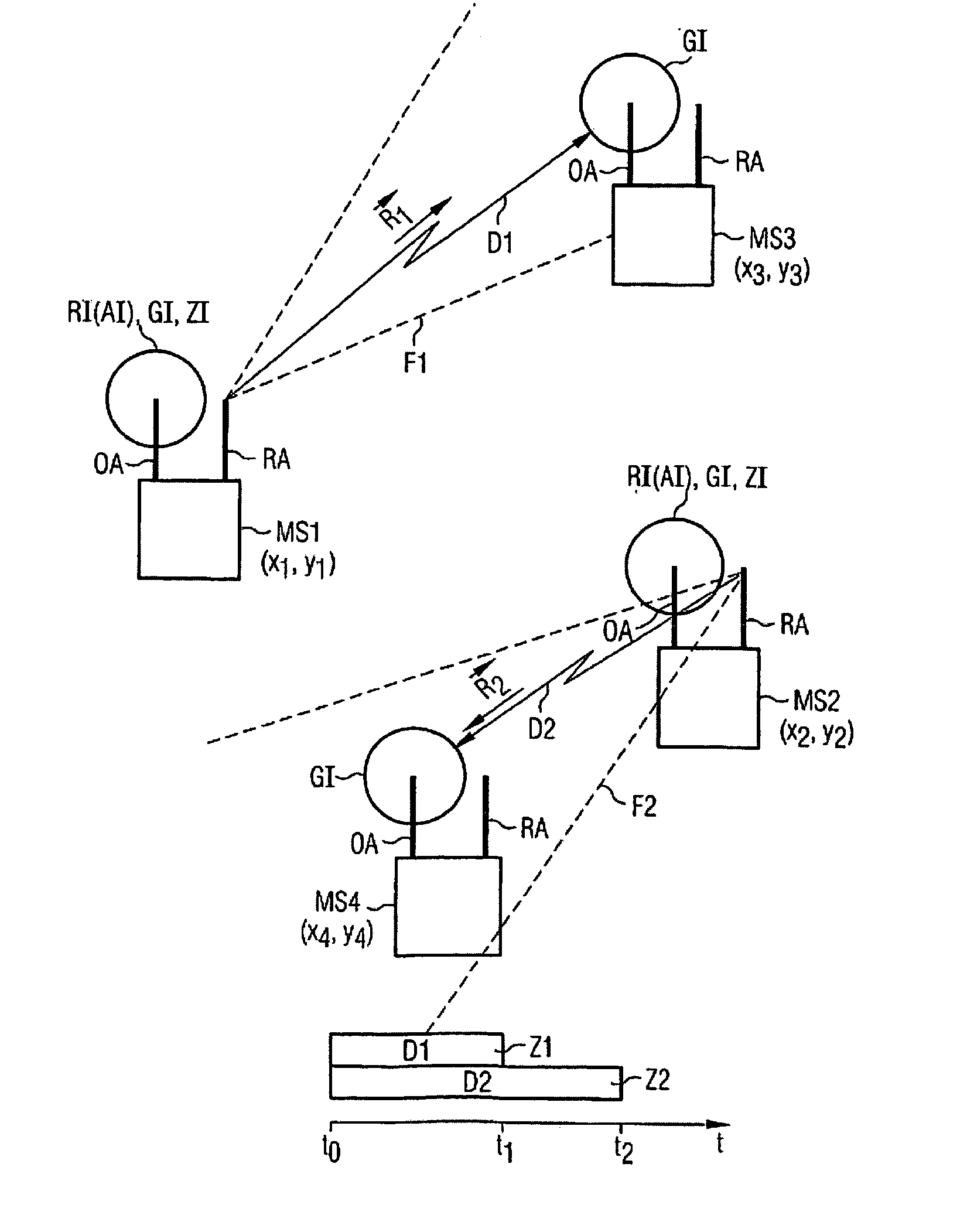
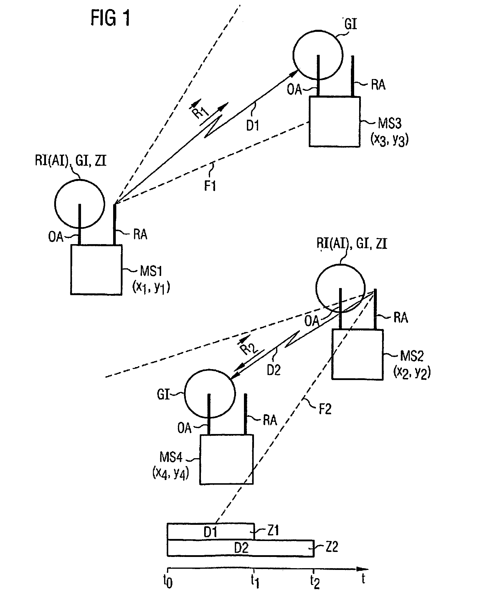
[0036] In the scheme shown in FIG. 1 a first emitting station MS1 and a second emitting station MS2 are depicted, as well as a first receiving station MS3 and a second receiving station MS4. The sending and the receiving stations MS1, MS2, MS3, MS4 each have a directional antenna RA and an omnidirectional antenna OA. If the receiving stations MS3, MS4 also have the same equipment which allows the emitting stations MS1, MS2 to execute the invention, the receiving stations MS3, MS4 can function in...


PUM


Abstract

In a radio system having stations which are at least partially provided with a directional antenna, a first emitting station is provided with a directional antenna in a first spatial radio area. The first emitting station sends a direction information message indicating the spatial direction in which the data is to be transmitted. Transmission resources can be advantageously occupied based on the direction information message.

Description

CROSS REFERENCE TO RELATED APPLICATIONS [0001] This application is based on and hereby claims priority to European Application No. 02018095.6 filed on Aug. 13, 2002, the contents of which are hereby incorporated by reference. BACKGROUND OF THE INVENTION [0002] 1. Field of the Invention [0003] The invention relates to a method for operating a radio system with at least some stations which are equipped with a directional antenna as well as to a corresponding emitting station and a corresponding radio system. [0004] 2. Description of the Related Art [0005] In radio systems both signaling data and organizational information (for example control signals or information about the quality of the connection) and also payload data (for example speech, picture information or other data) is transmitted by electromagnetic waves over a radio interface between sending and receiving station. [0006] Radio systems are for example cellular mobile radio systems such as GSM (Global system for Mobile com...

Claims


Application Information

Patent Timeline
IPC IPC(8): H04Q7/20H04M1/00H04L12/28H04L12/56H04W16/24H04W16/28H04W48/08
CPCH04W16/24H04W48/08H04W16/28
Inventor HALFMANN, RUDIGERLI, HUILOTT, MATTHIASSCHULZ, EGON
Owner SIEMENS AG
Why Eureka
Try Eureka