
Pressurized steam-jetting nozzle, and method and apparatus for producing nonwoven fabric using the nozzle

a technology of steam jet and nozzle, which is applied in the direction of lighting and heating apparatus, drying machines, drying machines with progressive movements, etc., can solve the problems of reducing the service life of the nozzle, and requiring a large amount of thermal energy, so as to facilitate the entanglement of the fibers and the other direction, and facilitating the entanglement

Active Publication Date: 2006-03-02
MITSUBISHI CHEM ENG CORP
View PDF1 Cites 24 Cited by
  • Summary
  • Abstract
  • Description
  • Claims
  • Application Information

AI Technical Summary

Benefits of technology

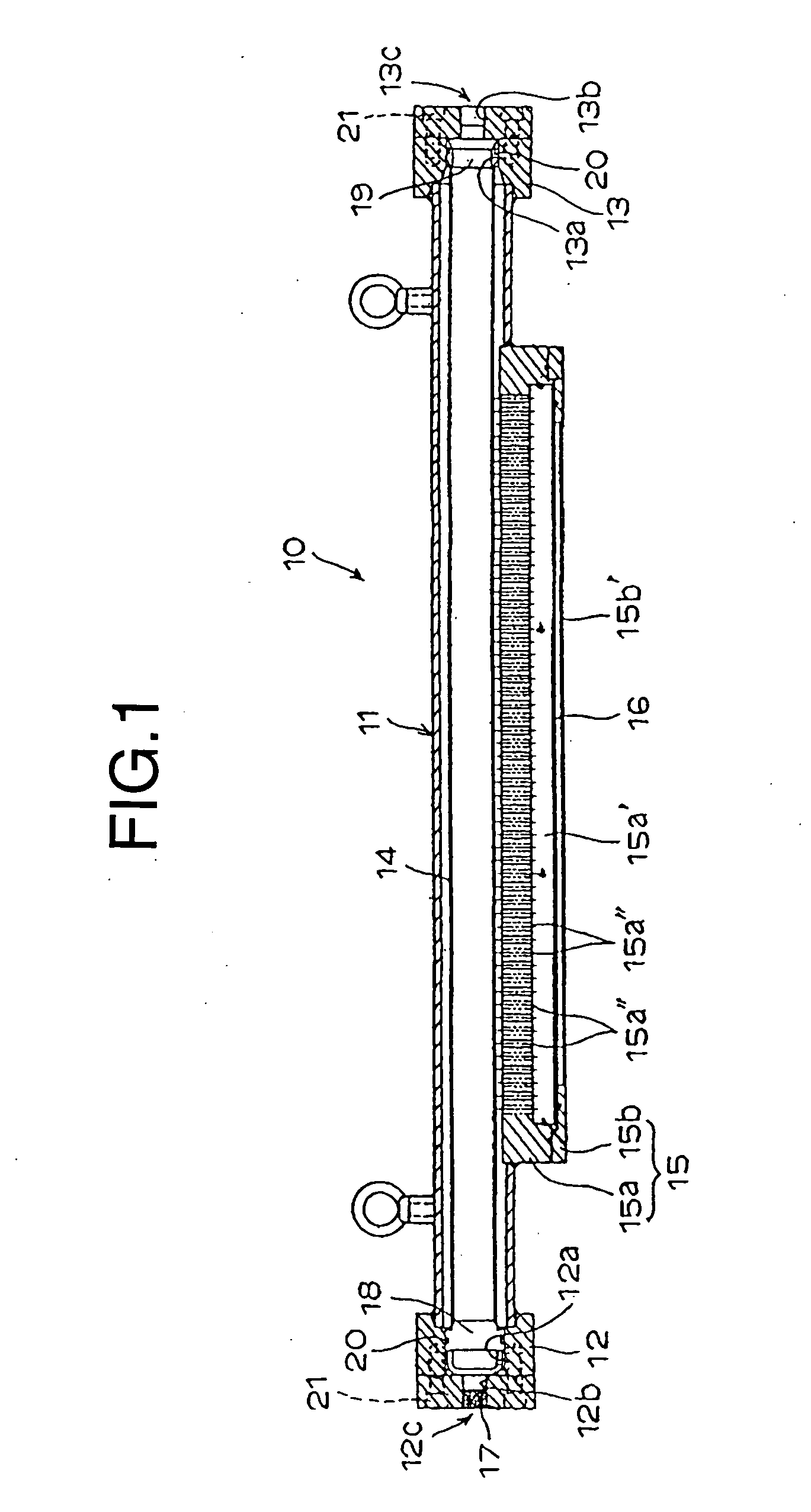
[0013] Therefore, according to the present invention, as mentioned above, the steam outlet opening is provided on another end of the nozzle holder so that the steam outlet opening is provided switchably by mounting for example an opening / closing valve, or the like as it is to be described later to the steam discharge tube connected with the steam outlet opening. At present, before starting a drive of the nonwoven fabric producing apparatus, the steam is introduced into the nozzle holder. At the time, the steam outlet opening is opened so that the steam introduced from the steam inlet opening is discharged continuously to the outside through the steam outlet opening. The nozzle holder temperature is measured so that the steam outlet opening is closed at a time the temperature reaches at a predetermined temperature. Simultaneously with a closure, the steam pressure at the steam inlet opening is measured so that, at the time the steam pressure reaches at the predetermined pressure, the nonwoven fabric production apparatus starts to be driven. A time to a start of the drive can be shortened dramatically compared with a case without the steam outlet opening as in the conventional embodiment by new high temperature steam passing through the nozzle holder because the temperature of the nozzle holder can be raised quickly.
[0044] If the trap conduit branched from the conduit of the steam discharging tube is provided as mentioned above, even after closing the opening / closing valve, the condensed liquid generated in the pressurized steam jetting nozzle, the minute foreign substances contained in the steam, or the like flows to the trap conduit via the steam discharging tube together with the condensed liquid so as to be discharged to the outside timely so that the steam can be jetted stably from the all nozzle holes without choking the nozzle holes by the condensed liquid or the minute foreign substances at a time of the drive of the apparatus. As the pressurized steam jetting nozzle to be adopted in the production method and the production apparatus of the present invention, the pressurized steam jetting nozzle of the present invention comprising the configurations already mentioned can be adopted. Moreover, although an example provided with one stage of the pressurized steam jetting nozzle has been described in the explanation, the steam jetting nozzle may be disposed in a multiple stages in a fiber web running direction. In this case, as it has already been described, by disposing the pressurized steam jetting nozzle and the vacuuming means thereof alternately on the front and rear sides with respect to the fiber web, a high quality nonwoven fabric with the stable surface state can be obtained.

Problems solved by technology

According to a production of an entangled nonwoven fabric by jetting a high pressure liquid flow, not only a liquid scattering prevention equipment is required due to a large liquid use amount and a purifying process equipment is required for the large amount of the liquid at a time of discharging the liquid after the process, but also a drying equipment for the obtained nonwoven fabric and a gigantic thermal energy consumed therefor are required.
Moreover, noise based on a liquid jetting operation is rampant so as to deteriorate a work environment.
Furthermore, since it passes through various kinds of tubes, or the like, extremely fine foreign substances can be mixed in the steam so that the jetting nozzle holes can easily be choked.
Furthermore, although the nozzle structure disclosed in the patent document 2 can be adopted preferably for a fluid flow jetting nozzle, a number of parts is too large so that it is too complicated for a steam jetting nozzle.

Method used


Image

  • Pressurized steam-jetting nozzle, and method and apparatus for producing nonwoven fabric using the nozzle
  • Pressurized steam-jetting nozzle, and method and apparatus for producing nonwoven fabric using the nozzle
  • Pressurized steam-jetting nozzle, and method and apparatus for producing nonwoven fabric using the nozzle

Examples


second embodiment

[0085] FIGS. 12 to 16 show the present invention. This embodiment differs from the embodiment including the first to fourth structure embodiments in that a nozzle member 23 does not comprise the first and second nozzle plate supporting members 15a, 15b as split pieces as in the other embodiments, but it comprises a single member such that nozzle holes 26 are formed directly in the nozzle member 23. Therefore, the nozzle plate 16 as an individual body as in the other embodiments is unnecessary.

[0086] An upper surface central part of the nozzle member 23 according to the second embodiment comprises a ship like recessed groove part 24 communicating with the slit like opening 11b elongating in the longitudinal direction formed in a lower surface center of the nozzle holder 11, a groove part 25 having a rectangular cross section, formed along a ship bottom part of the recessed groove part 24, a plurality of inverse truncated conical holes 26a formed by a predetermined pitch along the lon...


PUM

PropertyMeasurementUnit
thicknessaaaaaaaaaa
inner diameteraaaaaaaaaa

Abstract

The present invention relates to a nozzle suitable for jetting high pressure and high temperature steam, and a method and an apparatus for producing an entangled nonwoven fabric using the nozzle. According to the apparatus, a steam inlet side main conduit (c1) and a steam outlet side conduit (c3) are connected with both end parts of a tubular nozzle holder (11) in a longitudinal direction provided integrally with nozzle members (15, 16, 23) having a plurality of nozzle holes (16a, 26). A steam outlet side conduit (c2) is provided with an opening / closing valve (55) and a trap conduit (57) is branched from a conduit at an upstream side from the opening / closing valve (55). By opening the opening / closing valve (55), a rapid temperature rise of the nozzle holder (11) can be enabled at a time of starting a production of a nonwoven fabric. Furthermore, even in the opening / closing valve (55) is closed in a regular operation, drainage generated inside the nozzle holder (11) can always be discharged to outside so that steam can be jetted stably and continuously, and thus a high quality entangled fiber nonwoven fabric can be produced continuously from the fiber web by the steam.

Description

TECHNICAL FIELD [0001] The present invention relates to a fluid jetting nozzle for jetting pressurized steam flow, a production method for a fiber entangled nonwoven fabric using the same and a production apparatus therefor. BACKGROUND ART [0002] Conventionally, a technique for producing an entangled nonwoven fabric by entangling constituent fibers with each other by jetting a high pressure fluid flow to a fabric web has been known as it is disclosed in for example Japanese Patent Application Laid-Open (JP-A) No. 51-133579 (patent document 1), JP-A No. 9-256254 (patent document 2), JP-A No. 2000-144564 (patent document 3), or the like. However, as the high pressure fluid disclosed in the patent documents 1 to 3, a high pressure liquid is used mainly. According to a production of an entangled nonwoven fabric by jetting a high pressure liquid flow, not only a liquid scattering prevention equipment is required due to a large liquid use amount and a purifying process equipment is requir...

Claims


Application Information

Patent Timeline
Patent Type & Authority Applications(United States)
IPC IPC(8): D04H1/46D04H5/02D02J1/08D04H1/492
CPCD04H1/465D04H18/04
Inventor TANIGUCHI, MASAHIROSUZUKI, TOMIOSHIMIZU, SHINICHI
Owner MITSUBISHI CHEM ENG CORP
Learn More