Method and apparatus for maintaining warm engine temperature

a technology for maintaining the temperature of the engine, applied in the direction of engine lubrication, vehicle heating/cooling devices, air-conditioning devices, etc., can solve the problems of difficult to start a cold engine, wear, and take a considerable period of time to reach the operating temperature, so as to reduce the output of the maintenance schedule and simplify the maintenance schedul

Inactive Publication Date: 2006-03-02
DRYAIR 2000
View PDF4 Cites 19 Cited by
  • Summary
  • Abstract
  • Description
  • Claims
  • Application Information

AI Technical Summary

Benefits of technology

[0014] In another embodiment, the invention consists of a fluid heater, a warm fluid circulation loop, one fluid to fluid heat exchanger and an engine fluid circulation loop. Each vehicle engine is then simply connected to the engine fluid circulation loop in parallel with the other engines. In this embodiment all of the engine fluids systems are connected together and the engine fluids of the different engines mix. This can complicate maintenance schedules and can prematurely foul the engine fluid of a vehicle engine by mixing it with a dirtier engine fluid from a different engine. Also, different engine fluid systems may have different resistances and this could cause some vehicles engines attached in parallel to the engine fluid circulation loop to get less warm engine fluid circulation through them and therefore will not be heated as much as other engines connected to the engine fluid circulation loop.
[0015] The present invention has the advantage of allowing one fluid heater to heat a number of different vehicle engines at the same time. This allows the present invention to be portable and moveable from one location to another location. In may be desirable to have the fluid heater comprise a burner heated by a carbon-based fuel, such as diesel

Problems solved by technology

In very cold weather, and with larger diesel engines such as those used in locomotives it can take a considerable period of time to reach operating temperature.
It is also often very difficult to start a cold engine in some conditions, and once started considerable wear takes place before the engine oil warms up enough to provide satisfactory lubrication.
Fuel costs for an idling locomotive engine are significant, and since the engine is running, unnecessary wear is taking place on engine parts.
Exhaust gas and coolant from the smaller engine, and inefficient pump operation, provide heat that is transferred to t

Method used


Image

  • Method and apparatus for maintaining warm engine temperature
  • Method and apparatus for maintaining warm engine temperature
  • Method and apparatus for maintaining warm engine temperature

Examples


Embodiment Construction

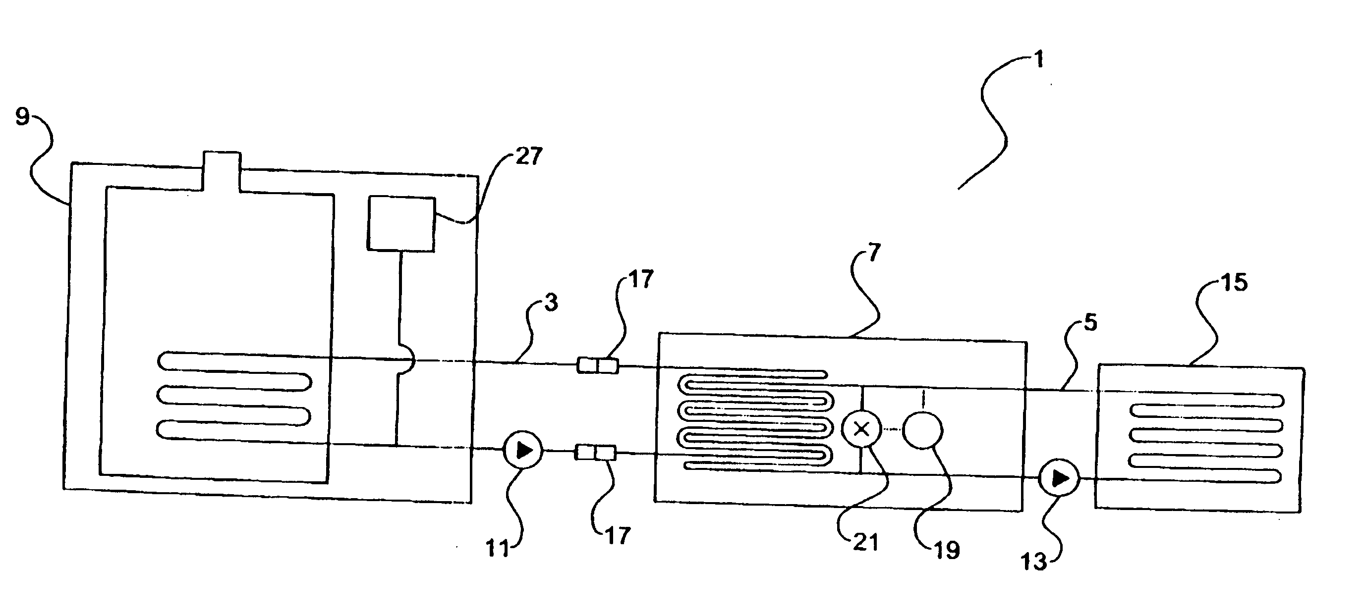
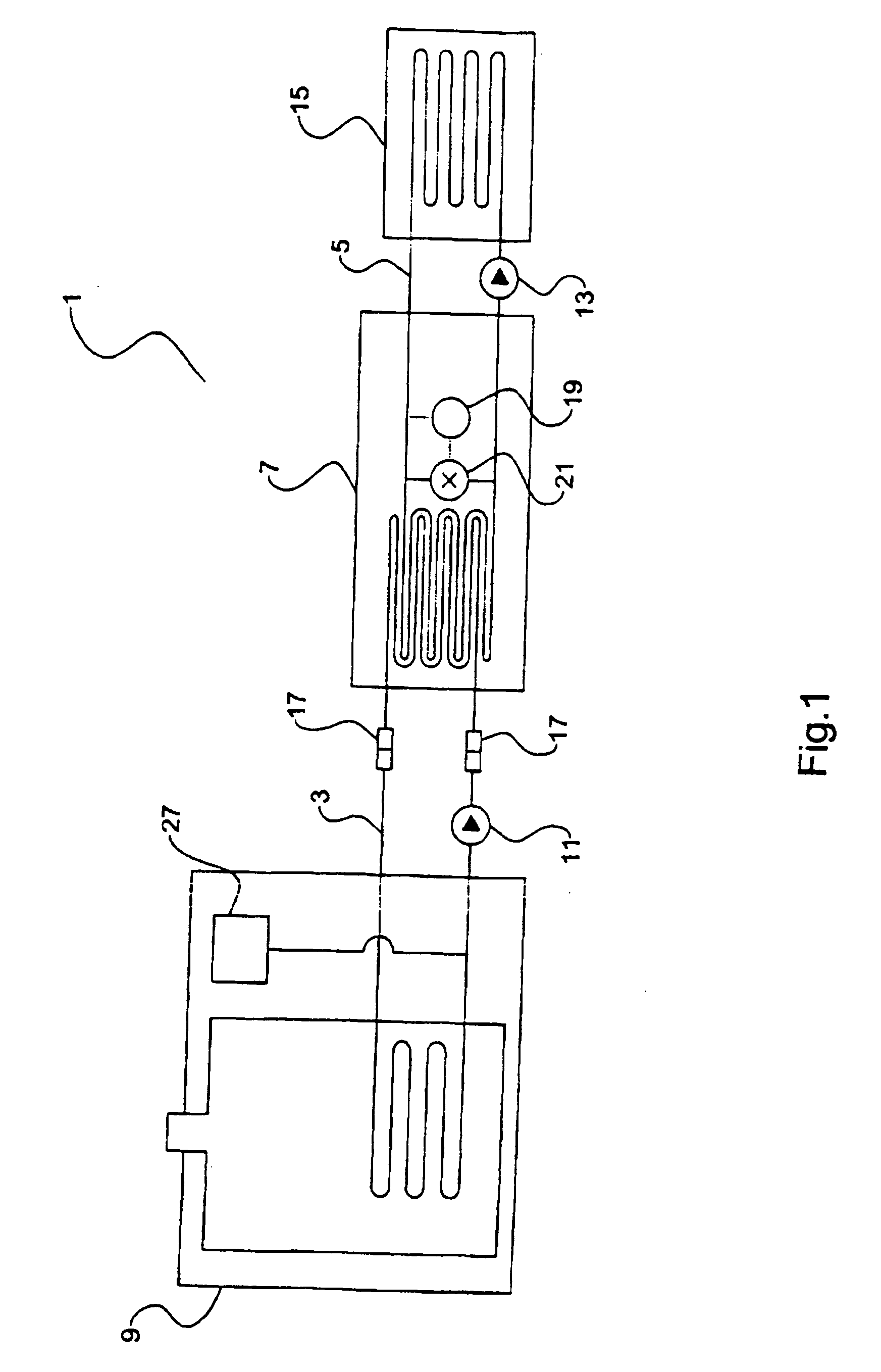
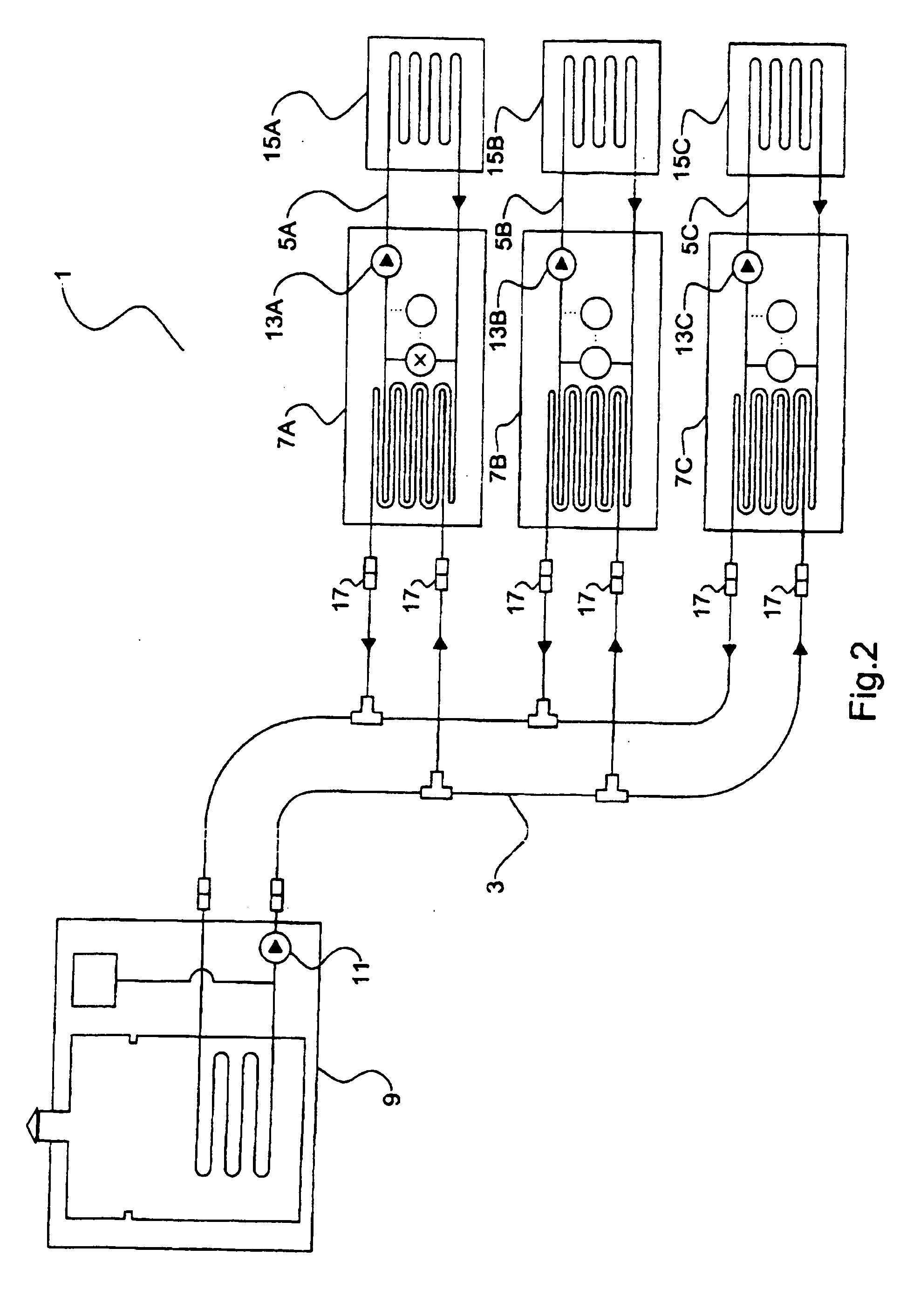
[0023]FIG. 1 schematically illustrates an apparatus 1 for temporarily warming a plurality of vehicle engines. The apparatus 1 comprises: a warm fluid circulation loop 3; an engine fluid circulation loop 5; a fluid heater 9; a fluid to fluid heat exchanger 7; a warm fluid pump 11; and an engine fluid pump 13.

[0024] The warm fluid circulation loop 3 is piping suitable for containing and transferring a warm fluid through its piping. The warm fluid circulation loop 3 connects the fluid heater 9 to the fluid to fluid heat exchanger 7. The warm fluid circulation loop 3 contains fluid which is suitable for being heated by the fluid heater 9 and sufficient for storing and transferring the heat.

[0025] The engine fluid circulation loop 5 comprises piping suitable for containing engine fluid. The engine fluid circulation loop 5 is connectable to at least one engine fluid system 15 in a vehicle engine (not shown) and transfers engine fluid from the engine fluid system 15 out of the engine veh...


PUM


Abstract

A portable apparatus for temporarily warming a plurality of vehicle engines includes a warm fluid circulation loop; an engine fluid circulation loop; a fluid heater; a fluid to fluid heat exchangers; a warm fluid pump; and an engine fluid pump. The warm fluid circulation loop connects the warm fluid heater to the fluid to fluid heat exchanger. The engine fluid circulation loop transfers engine fluid from engine fluid systems to the fluid to fluid heat exchanger. The fluid heater heats the fluid in the warm fluid circulation loop and the warm fluid is then circulated through the warm fluid circulation loop to the fluid to fluid heat exchanger to warm the engine fluid in the engine fluid circulation loop. The warmed engine fluid circulates through the engine fluid system warming the vehicle engine. The apparatus is configured to warm a plurality of vehicle engines at the same time.

Description

[0001] This invention is in the field of internal combustion engines, and in particular the operation of larger engines, such as locomotive engines, in cold weather. BACKGROUND [0002] When starting internal combustion engines in cold weather it is desirable to let the engine idle for a period of time in order to bring the engine up to a satisfactory operating temperature before putting it to work. In very cold weather, and with larger diesel engines such as those used in locomotives it can take a considerable period of time to reach operating temperature. It is also often very difficult to start a cold engine in some conditions, and once started considerable wear takes place before the engine oil warms up enough to provide satisfactory lubrication. For these reasons locomotive engines are often not shut down at all but left idling continuously emitting exhaust into the environment. Fuel costs for an idling locomotive engine are significant, and since the engine is running, unnecessa...

Claims


Application Information

Patent Timeline
IPC IPC(8): F02N17/02F02N19/02F02N19/04
CPCF02N19/10F01M5/021
Inventor BOURGAULT, CLAUDEDANCEY, LARRY
Owner DRYAIR 2000
Why Eureka
Try Eureka