Engine coolant changing system

Inactive Publication Date: 2006-03-02
DOTY ROBERT A +2
View PDF5 Cites 6 Cited by
  • Summary
  • Abstract
  • Description
  • Claims
  • Application Information

AI Technical Summary

Benefits of technology

[0001] There has long existed a need for a coolant removal and replacement system which is multi-functional an

Problems solved by technology

Prior art methods for removal and replacement of coolant have typically involved a cone-shaped adapter inserted in the vehicle radiator service opening, which arrangement does not allow the escape of air trapped in the coolant system, particularly when partial vacuum is employed to draw the coolant into the system.
A problem presen

Method used


Image

  • Engine coolant changing system
  • Engine coolant changing system
  • Engine coolant changing system

Examples


Embodiment Construction

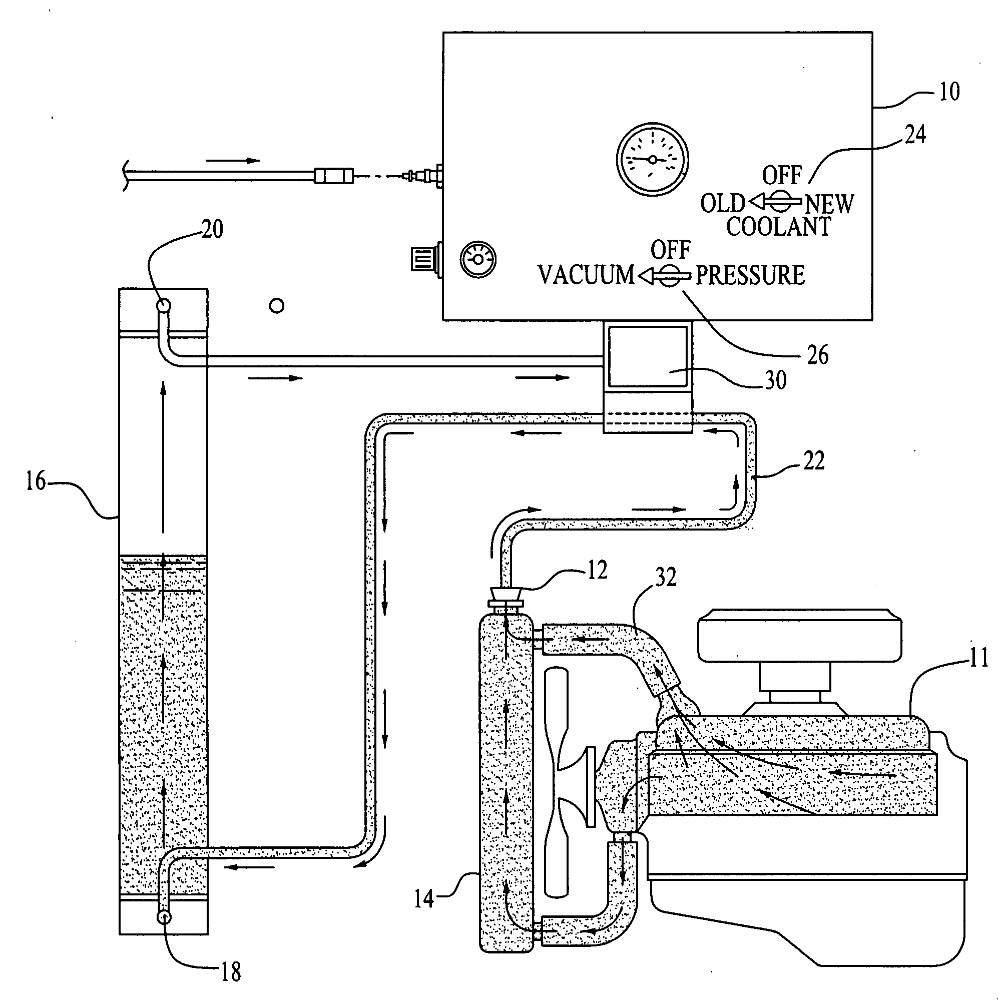
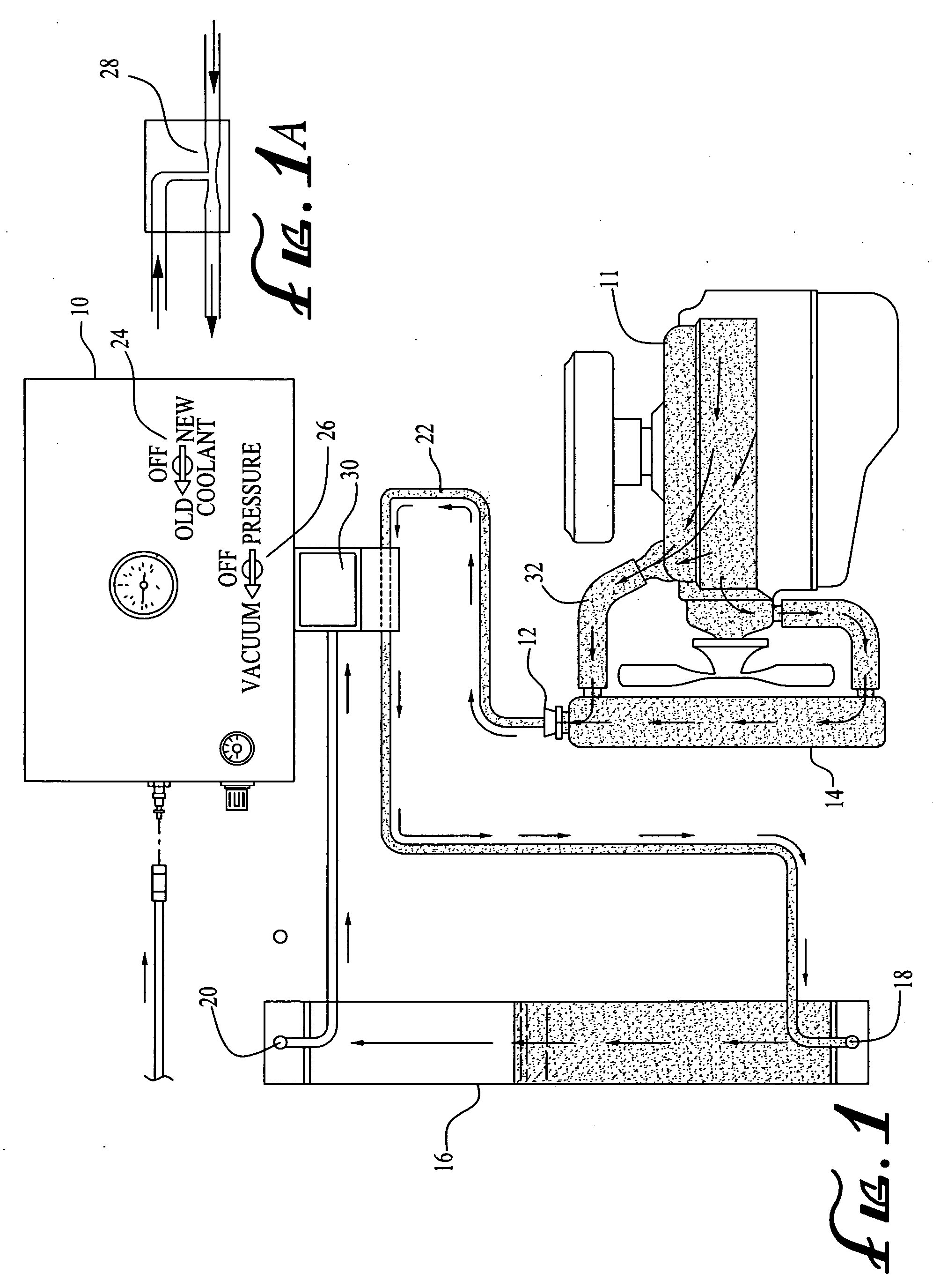
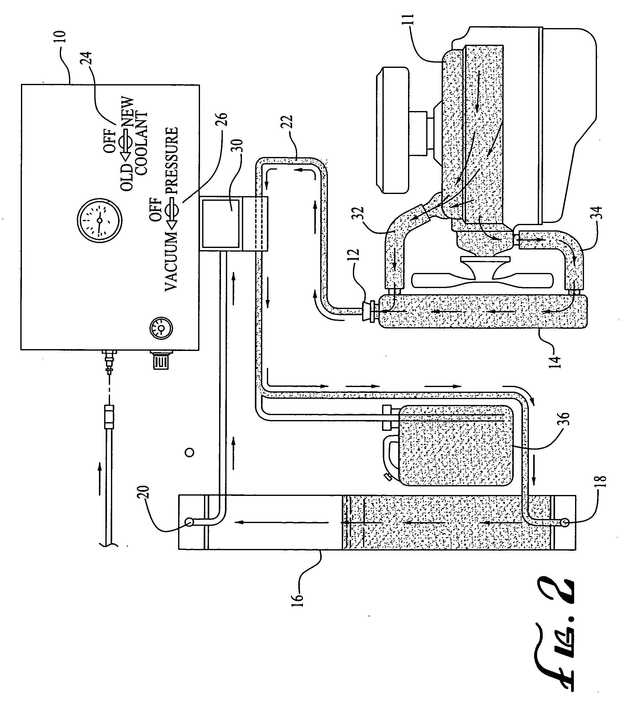
[0015] The present invention relates to systems for removal of old coolant from a vehicle engine and replacement thereof with new coolant.

[0016] The process of removing old coolant is accomplished by utilizing suction and partial vacuum at a venturi to provide a partial vacuum in tubes of the system of the invention, thereby insuring spill-free service which is essential in view of environmental concerns and EPA regulations regarding disposal of antifreeze compounds.

[0017] The present invention involves three embodiments and methods. The first and simpler method utilizes a storage tube and a venturi, with interconnecting hoses and valvings.

[0018] A second embodiment of the invention comprises the components of the first embodiment, and a removable container or bottle and connected with a pump.

[0019] A third or advanced embodiment utilizes the components of the first two embodiments, together with a stepped adapter for attachment to a radiator or hose.

[0020] Referring to the dra...


PUM

PropertyMeasurementUnit
Pressureaaaaaaaaaa
Flow rateaaaaaaaaaa
Sizeaaaaaaaaaa

Abstract

An engine cooling system liquid insertion and removal system has an adapter disposed in a vehicle radiator service opening via which old coolant is removed from the engine system by partial vacuum applied to an old coolant container via a conduit. New coolant is introduced via the adapter by atmospheric pressure from a portable container. Conduits interconnect the engine cooling system, the old and new coolant containers, and a source of partial vacuum applied to conduits.

Description

BACKGROUND AND SUMMARY OF THE INVENTION [0001] There has long existed a need for a coolant removal and replacement system which is multi-functional and provides prompt, efficient extraction of coolant and the insertion of new coolant in a vehicle engine system. [0002] That is, there has existed a need for such a system which can accommodate the relatively simple function of extracting old coolant and the insertion of new coolant without requiring any coolant service apparatus which requires multiple tubes and other complications. [0003] The present invention provides a single tube system preferably utilized with a multi-gallon portable container which enables the utilization of multiple types of coolant by simply replacing one container with another. [0004] Prior art methods for removal and replacement of coolant have typically involved a cone-shaped adapter inserted in the vehicle radiator service opening, which arrangement does not allow the escape of air trapped in the coolant sy...

Claims


Application Information

Patent Timeline
IPC IPC(8): B65B3/04
CPCF01P11/0276F01P11/0204
Inventor FLYNN, ROBERT E.
Owner DOTY ROBERT A
Why Eureka
Try Eureka