

Method of forming an optical pattern, optical pattern formation system, and optical tweezer
a technology of optical pattern and optical pattern, applied in the field of optical pattern formation method, optical pattern formation system, etc., can solve the problem that the shape of optical pattern formed by the above techniques is limited to those adequately separated from the 0-order ligh
- Summary
- Abstract
- Description
- Claims
- Application Information
AI Technical Summary
Benefits of technology
Problems solved by technology
Method used
Image

Examples
first embodiment
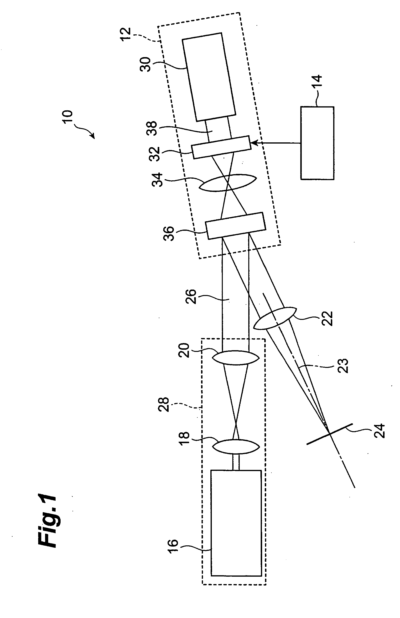
[0039]FIG. 1 is a schematic diagram showing the configuration of an optical pattern formation system 10 in the first embodiment of the present invention. The optical pattern formation system 10 has a spatial light modulator 12, a controller 14, a reading light source 16, a beam expander 18, a collimator lens 20, and a Fourier transform lens 22, and is able to form a desired two-dimensional optical pattern on an output plane 24.
[0040] The spatial light modulator 12 is an example of the phase-modulating spatial light modulator of an electrically addressing type and is called a PPM (Programmable Phase Modulator). The spatial light modulator 12 has a writing light source 30, a transmissive LCD (Liquid Crystal Display) 32, an imaging lens 34, and a PAL-SLM (Parallel-Aligned Nematic Liquid Crystal Spatial Light Modulator) 36.
[0041] The writing light source 30 emits writing light 38 of a plane wave having a uniform two-dimensional intensity distribution, onto the LCD 32. The writing ligh...
second embodiment
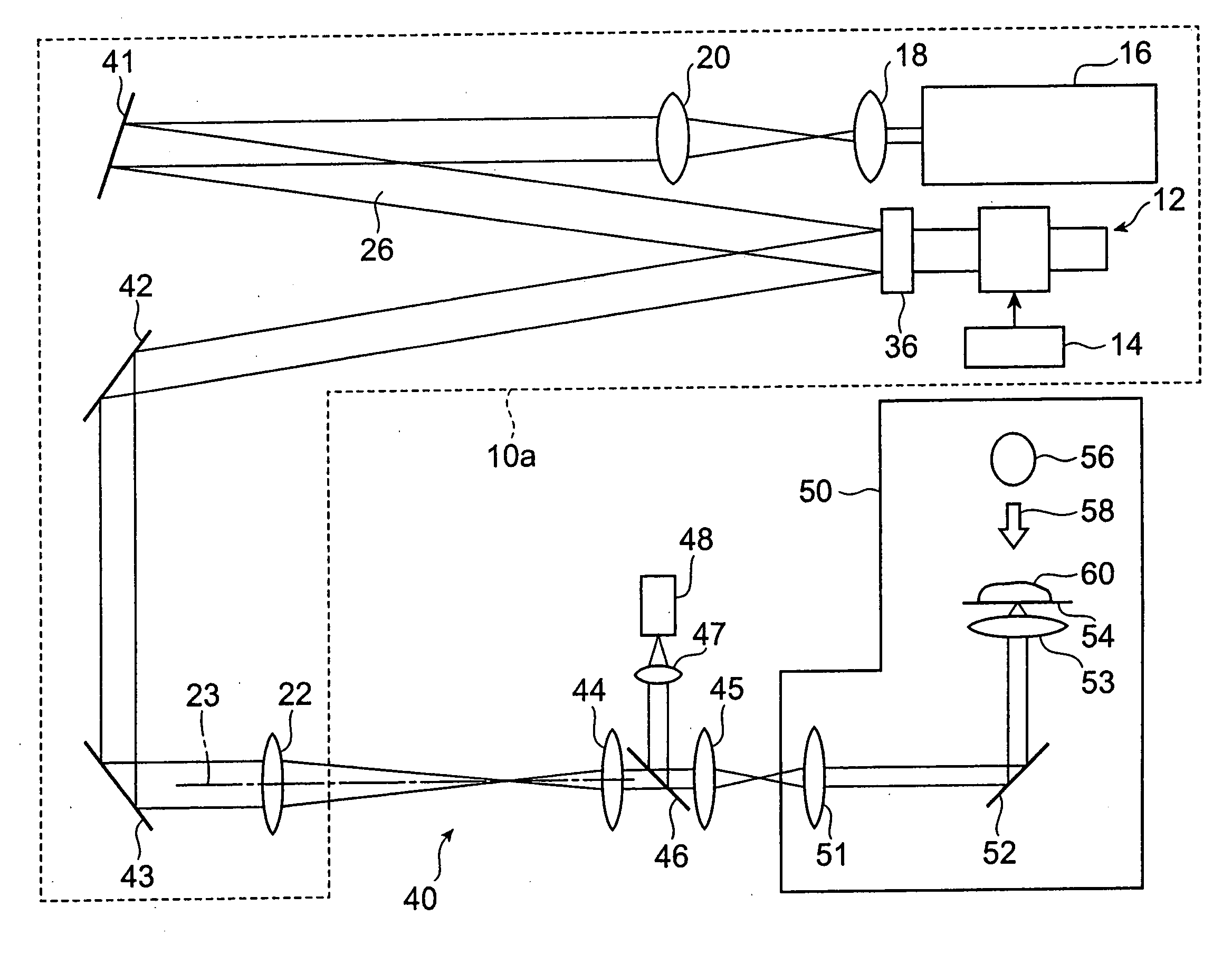
[0061] The second embodiment of the present invention will be described below. FIG. 6 is a schematic diagram showing the configuration of an optical pattern formation system in the present embodiment. This optical pattern formation system 40 uses an optical pattern formation system 10a similar to the first embodiment to form an optical pattern and focus an image of the optical pattern on an observation plane in a microscope 50.
[0062] Mirrors 41-43 for reflecting the reading light 26 are arranged in the optical pattern formation system 10a. An image of the optical pattern formed by the optical pattern formation system 10a is transferred into the microscope 50 by relay lenses 44 and 45. This optical pattern is projected onto a bottom surface of a sample stage 54 by a relay lens 51, mirror 52, and objective lens 53 in the microscope 50. The sample stage 54 is provided with a window (not shown) for transmitting the optical pattern, and the optical pattern passes through this window to ...
third embodiment
[0067] The third embodiment of the present invention will be described below. FIG. 8 is a schematic diagram showing the configuration of an optical pattern formation system in the present embodiment. This optical pattern formation system 70 has a configuration that is obtained by adding a phase plate 21 on the optical path between collimator lens 20 and PAL-SLM 36 in the optical pattern formation system 10 of the first embodiment. In the present embodiment, therefore, the light emitting device 28 is configured of the phase plate 21 as well as the reading light source 16, beam expander 18, and collimator lens 20. The reading light 26 is emitted from the reading light source 16 and travels through the beam expander 18, collimator lens 20, ad phase plate 21 to irradiate the PAL-SLM 36.
[0068] The phase plate 21 is a transmissive phase-modulating spatial light modulator. The phase plate 21 provides an irregular phase distribution to the wavefront of the plane wave transmitted by the pha...
PUM
 Abstract
Description
Claims
Application Information