Magnetic motion sensor
- Summary
- Abstract
- Description
- Claims
- Application Information
AI Technical Summary
Benefits of technology
Problems solved by technology
Method used
Image


Examples
first embodiment
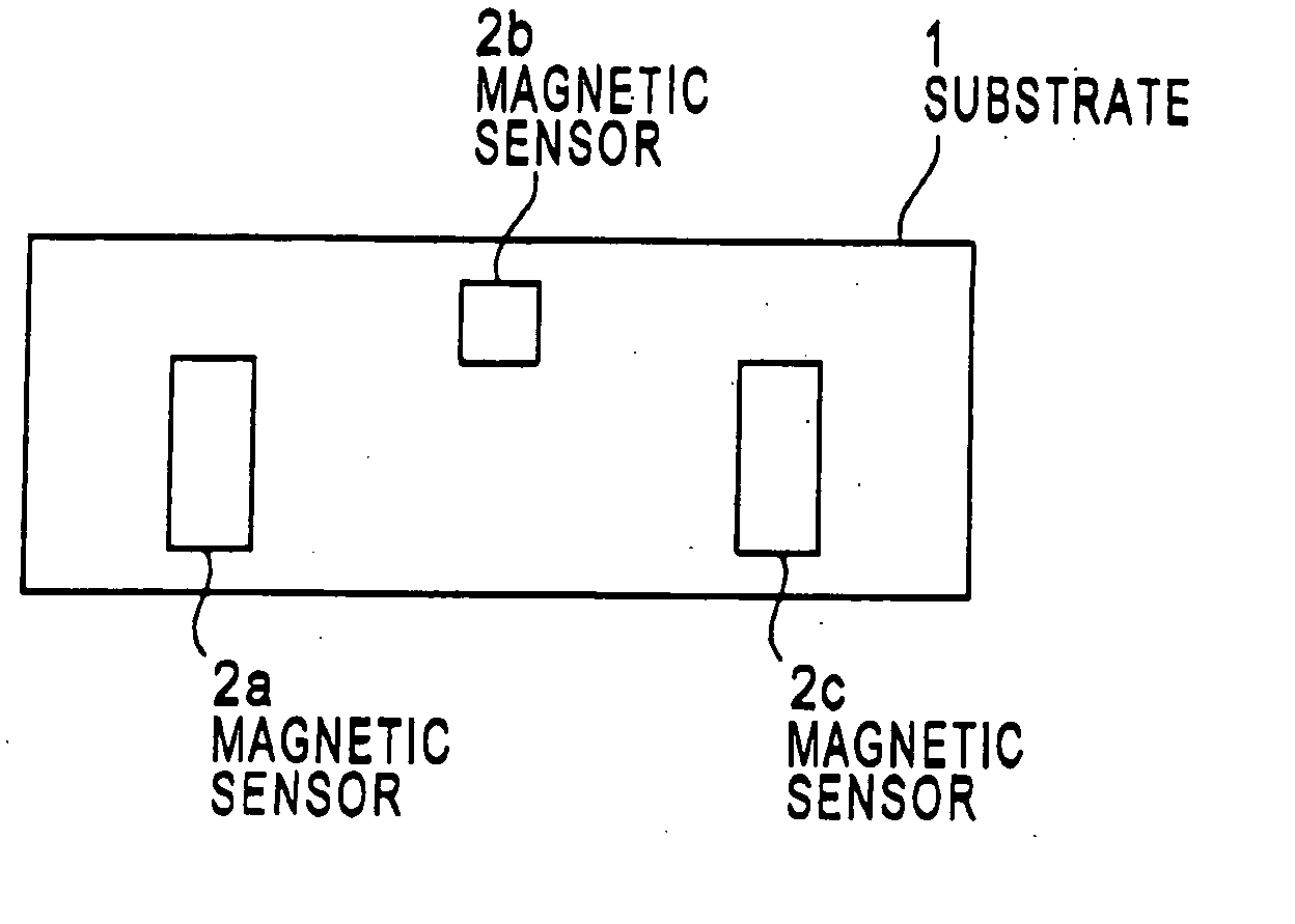
[0068]FIG. 1A shows a magnetic motion sensor in a first preferred embodiment according to the invention. The magnetic motion sensor is provided with two magnetic sensors 2a and 2c arranged in parallel along the longitudinal direction of a substrate 1 on the surface thereof, an auxiliary magnetic sensor 2b disposed in between the magnetic sensors 2a and 2c wherein the auxiliary magnetic sensor 2b is positioned out of the alignment of the magnetic sensors 2a and 2c, and a circuit (not shown) disposed in an area where the magnetic sensors 2a, 2b, and 2c do not exist in the surface of the substrate 1. The magnetic sensors 2a, 2b, and 2c are, for example, Hall elements wherein the two magnetic sensors 2a and 2c have the same shapes and the same dimensions, and sensitivities with respect to magnetism are the same, as a matter of course. On one hand, since the magnetic sensor 2b has different functions from that of the magnetic sensors 2a and 2c as mentioned hereunder, the magnetic sensor ...
second embodiment
[0070]FIG. 1B shows a magnetic motion sensor in a second preferred embodiment according to the invention. The magnetic motion sensor is provided with three magnetic sensors 4a, 4b, and 4c aligned in parallel along the longitudinal direction of a substrate 3 on the surface thereof, and a circuit (not shown) disposed in an area where the magnetic sensors 4a, 4b, and 4c do not exist in the surface of the substrate 3. The magnetic sensors 4a, 4b, and 4c are, for example, Hall elements. The three magnetic sensors 4a, 4b, and 4c have the same shapes and dimensions, and their orientations, sensitivities, and temperature characteristics are the same, respectively, as a matter of course. This magnetic motion sensor may be applied to the rotation sensor shown in FIG. 19 or FIG. 20 as in the case of FIG. 1A.
[0071] A circuit constitution suitable for the magnetic motion sensor of FIG. 1A is shown in FIG. 2B, while a circuit constitution suitable for the magnetic motion sensor of FIG. 1B is sho...
PUM
 Abstract
Description
Claims
Application Information