
Method and apparatus for low voltage temperature sensing

Active Publication Date: 2006-03-02
MICRON TECH INC
View PDF15 Cites 31 Cited by
  • Summary
  • Abstract
  • Description
  • Claims
  • Application Information

AI Technical Summary

Benefits of technology

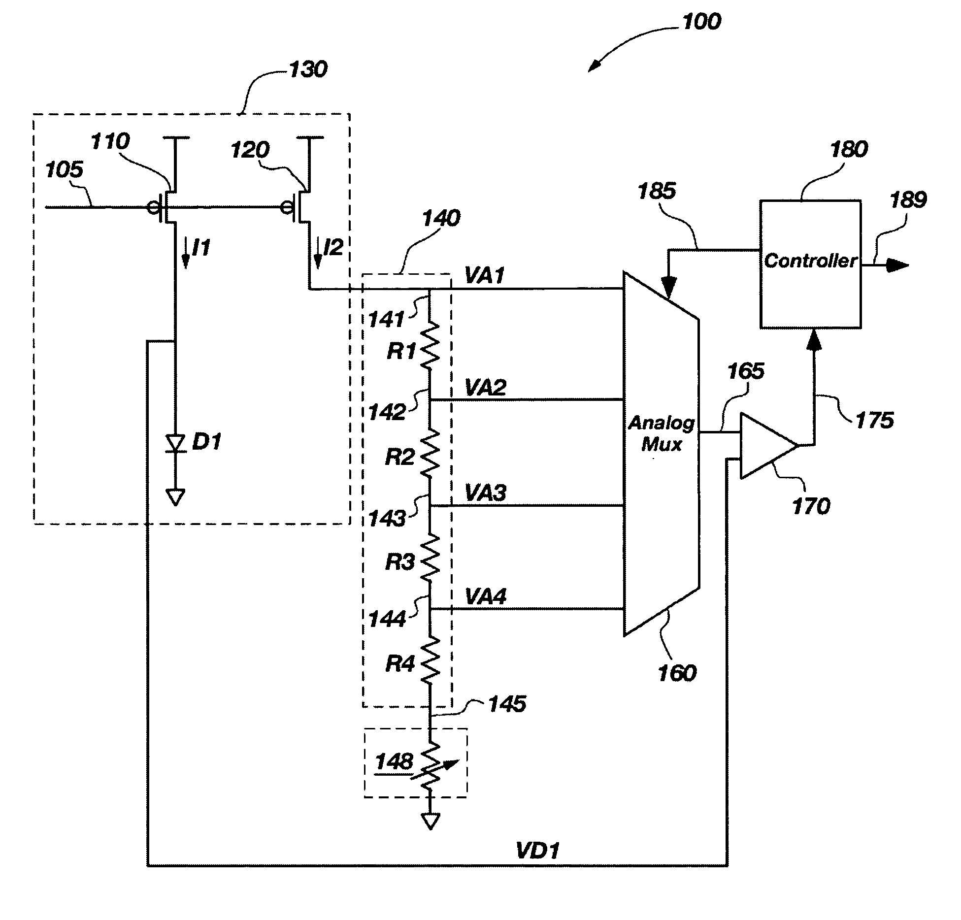
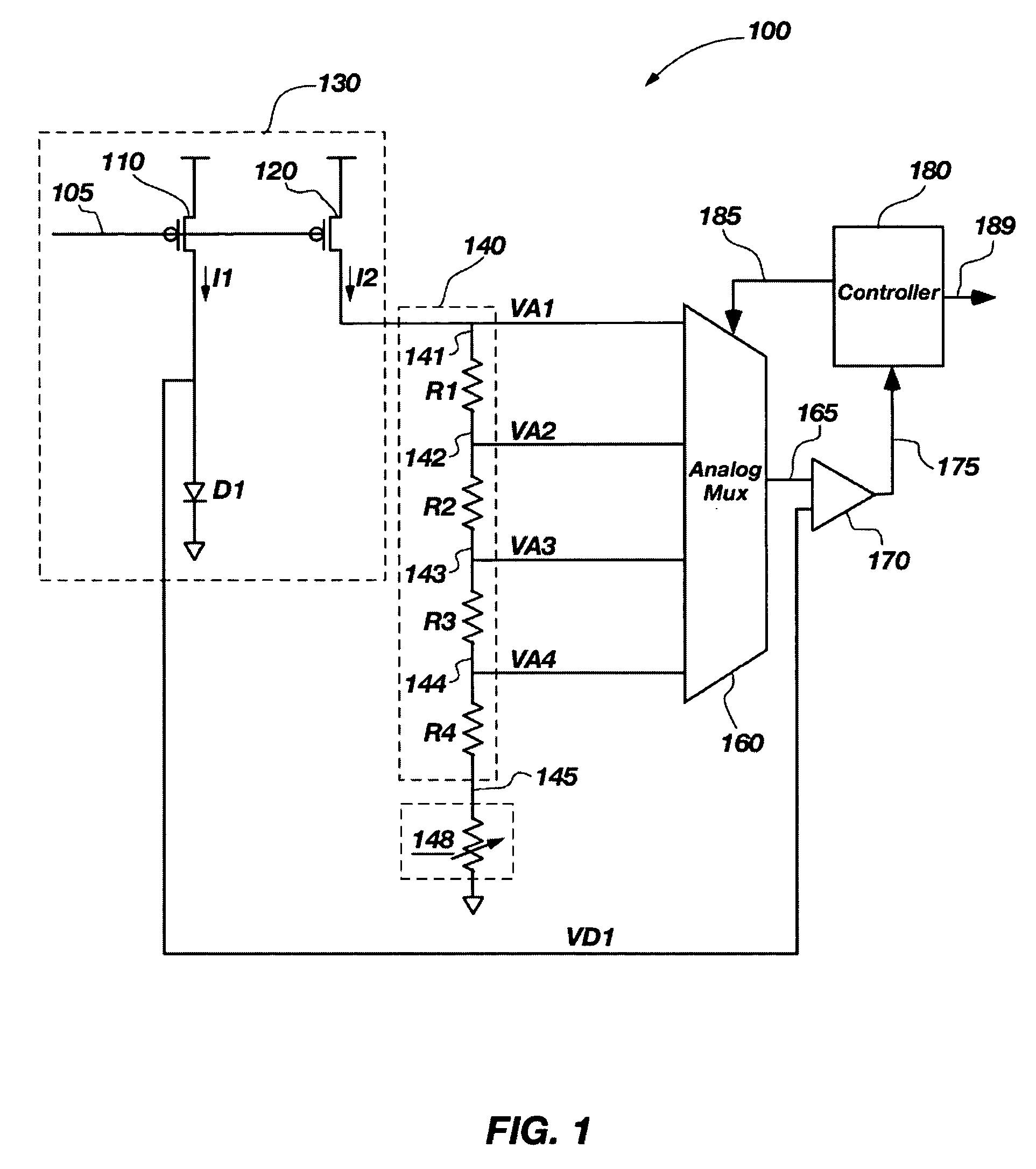
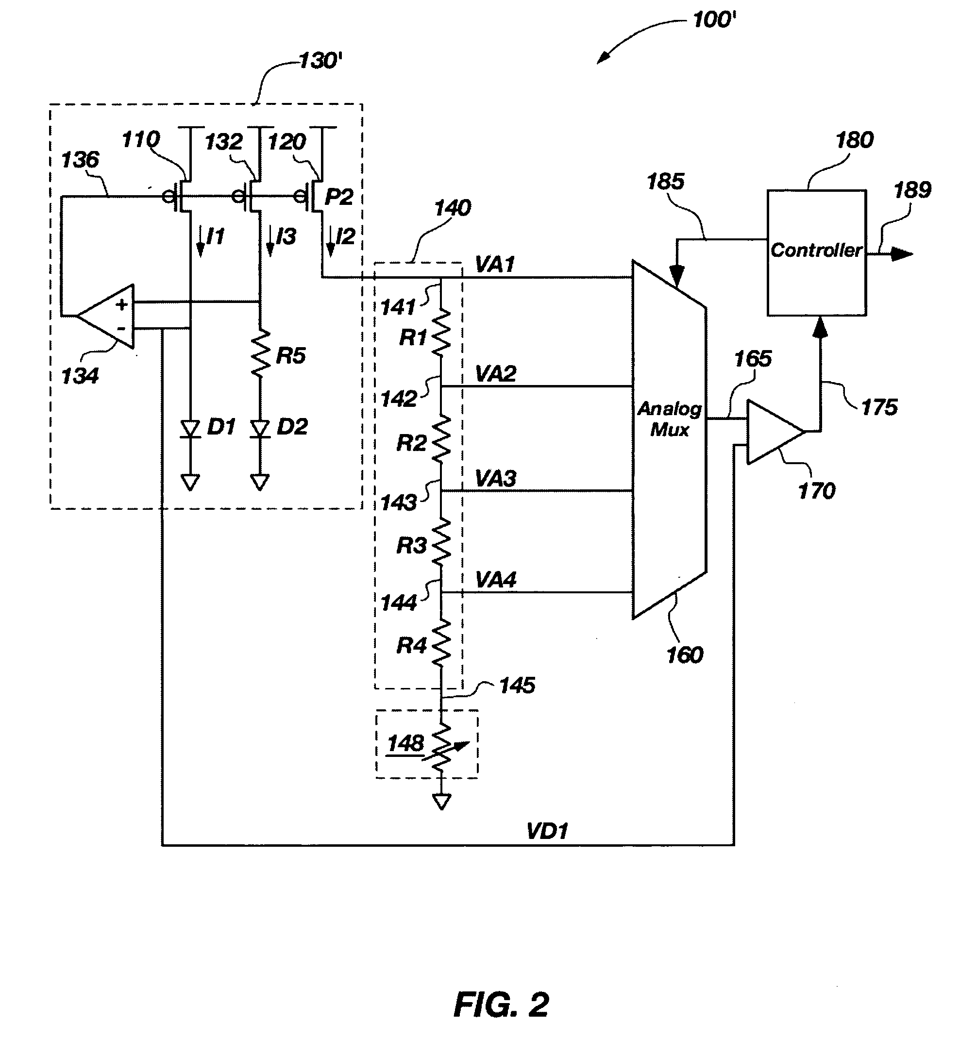
[0009] The present invention enables simple temperature sensing at a variety of temperatures and at lower voltages. An embodiment of the present invention comprises a temperature sensor including a reference module, a resistor stack, a plurality of analysis signals connected to the resistor stack, an analog multiplexer, a comparator, and a controller. The reference module may be configured for generating a reference voltage inversely correlated to a temperature. The resistor stack includes a plurality of resistors operably coupled in series between a reference current and a base signal, wherein each analysis signal comprises a voltage drop acros

Problems solved by technology

The increased toggling frequencies generate additional heat, which may cause a semiconductor device to reach very hig

Method used


Image

  • Method and apparatus for low voltage temperature sensing
  • Method and apparatus for low voltage temperature sensing
  • Method and apparatus for low voltage temperature sensing

Examples


Embodiment Construction

[0025] In the following description, circuits and functions may be shown in block diagram form in order not to obscure the present invention in unnecessary detail. Conversely, specific circuit implementations shown and described are exemplary only, and should not be construed as the only way to implement the present invention unless otherwise specified herein. Additionally, block definitions and partitioning of logic between various blocks is exemplary of a specific implementation. It will be readily apparent to one of ordinary skill in the art that the present invention may be practiced by numerous other partitioning solutions. For the most part, details concerning timing considerations and the like have been omitted inasmuch as such details are not necessary to obtain a complete understanding of the present invention and are within the abilities of persons of ordinary skill in the relevant art.

[0026] The term “bus” is used to refer to a plurality of signals or conductors, which m...


PUM


Abstract

A temperature sensor device and method of sensing temperature are disclosed. The device and method include generating a reference voltage inversely correlated to the temperature, generating a plurality of analysis voltages correlated to the temperature using a reference current, comparing the reference voltage to each of the plurality of analysis voltages, and generating a temperature estimate based on the comparison. The device and method may also include a method to selectively bypass various resistors in a resistor stack used to generate the various analysis voltages. Another embodiment of the present invention comprises a semiconductor device including at least one temperature sensor according to the invention described herein. The temperature sensor and method of sensing temperature may be incorporated into a semiconductor device, which may be fabricated on a semiconductor wafer and included in an electronic system.

Description

BACKGROUND OF THE INVENTION [0001] 1. Field of the Invention [0002] This invention relates generally to temperature sensors, and particularly to determining various temperature points using a reduced voltage. [0003] 2. Description of Related Art [0004] In modem high frequency integrated circuits, operating temperature has become increasingly important. Power consumption and device temperatures may generally be related to clock frequency and the number of nodes on a semiconductor device toggling at these high frequencies. The increased toggling frequencies generate additional heat, which may cause a semiconductor device to reach very high temperatures. Generally, devices are specified to operate in a certain temperature range within which the device has been characterized. Temperature sensors on these devices may be useful to control the operational parameters of the device. For example, if the temperature of the device rises above a temperature threshold, operation of the device may...

Claims


Application Information

Patent Timeline
IPC IPC(8): H01L35/00
CPCG01K2219/00G01K7/015
Inventor PORTER, J. DAVID
Owner MICRON TECH INC
Learn More