Bidirectional thermal expansion valve

A thermal expansion valve, valve body technology, applied in the direction of lift valve, valve details, valve device, etc., can solve the problems of high failure rate, poor sealing performance, small cooling (heat) capacity, etc., achieve good sealing performance, improve sealing Good performance and sealing quality

Inactive Publication Date: 2007-10-03
View PDF8 Cites 0 Cited by
  • Summary
  • Abstract
  • Description
  • Claims
  • Application Information

AI Technical Summary

Problems solved by technology

Its disadvantage is high cost and high failure rate
[0004] 2. In the small-capacity vapor compression heat pump system, that is, the room air conditioner, two capillary tubes, a tee and a one-way valve are used to form a throttling device. Although it has the advantages of simple structure, reliability, and low cost, it is only used in the only It can only operate economically when it works in a design condition, and when it operates in a non-design condition, the cooling (heat) amount is small and the energy efficiency ratio is low
[0005] 3. A thermal expansion valve composed of a bellows, a valve body, a valve needle, a valve core, a balance spring, and an adjusting stud is used. Due to the defects in the above-mentioned structural design, the thermal expansion valve can only work in one direction, and is externally sensed. , that is, use an external temperature-sensing tube to sense the temperature. The temperature-sensing tube is connected to the membrane box through the connecting tube. The temperature sensing deviation is large and the sealing performance is poor.
In order to solve the two-way work, a throttling device consisting of two thermal expansion valves and two one-way valves, or one thermal expansion valve and four one-way valves is adopted. Although it can effectively achieve two-way throttling, the structure is relatively complicated and the cost is low. high

Method used


Image

  • Bidirectional thermal expansion valve
  • Bidirectional thermal expansion valve
  • Bidirectional thermal expansion valve

Examples


Embodiment Construction

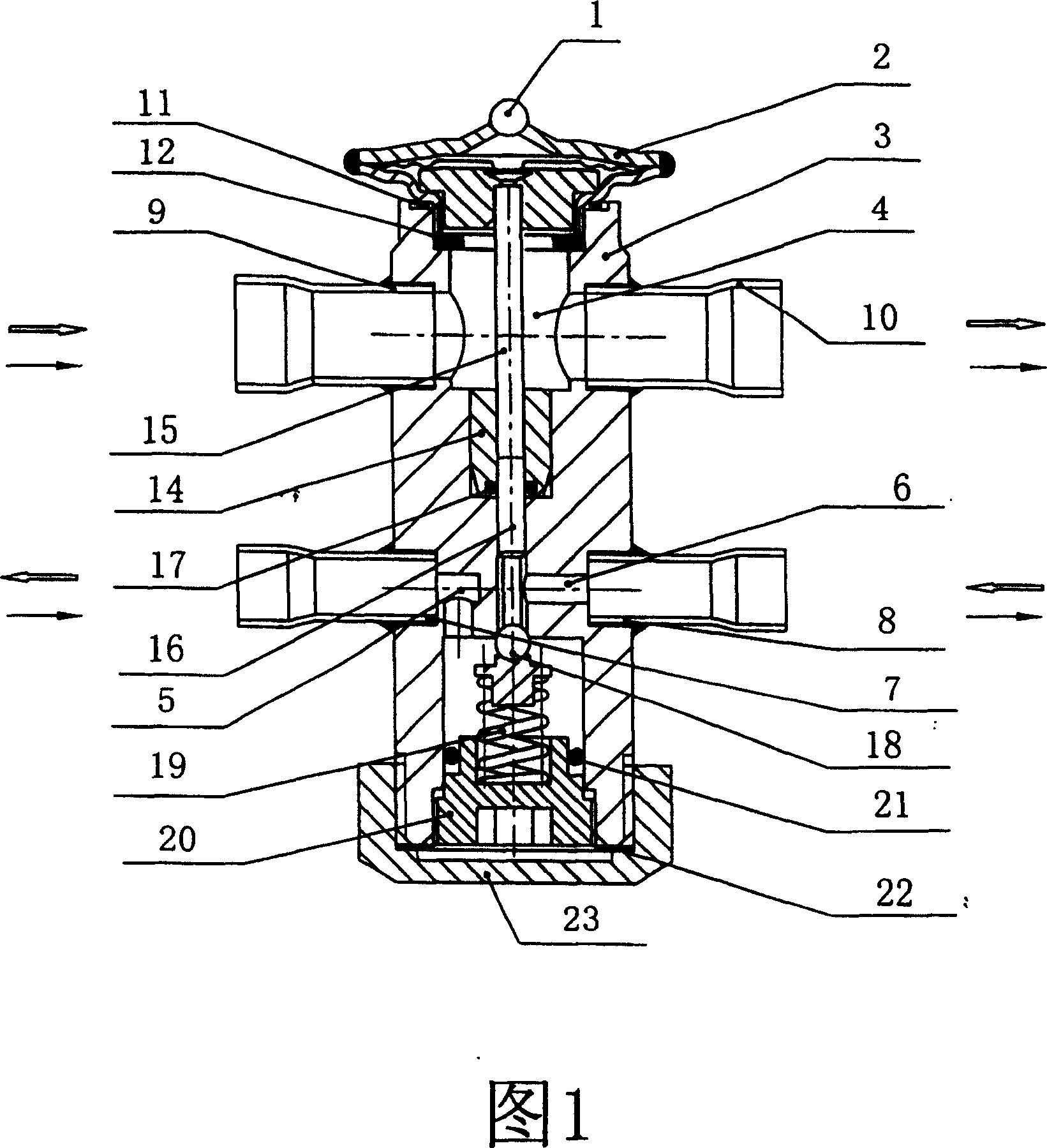
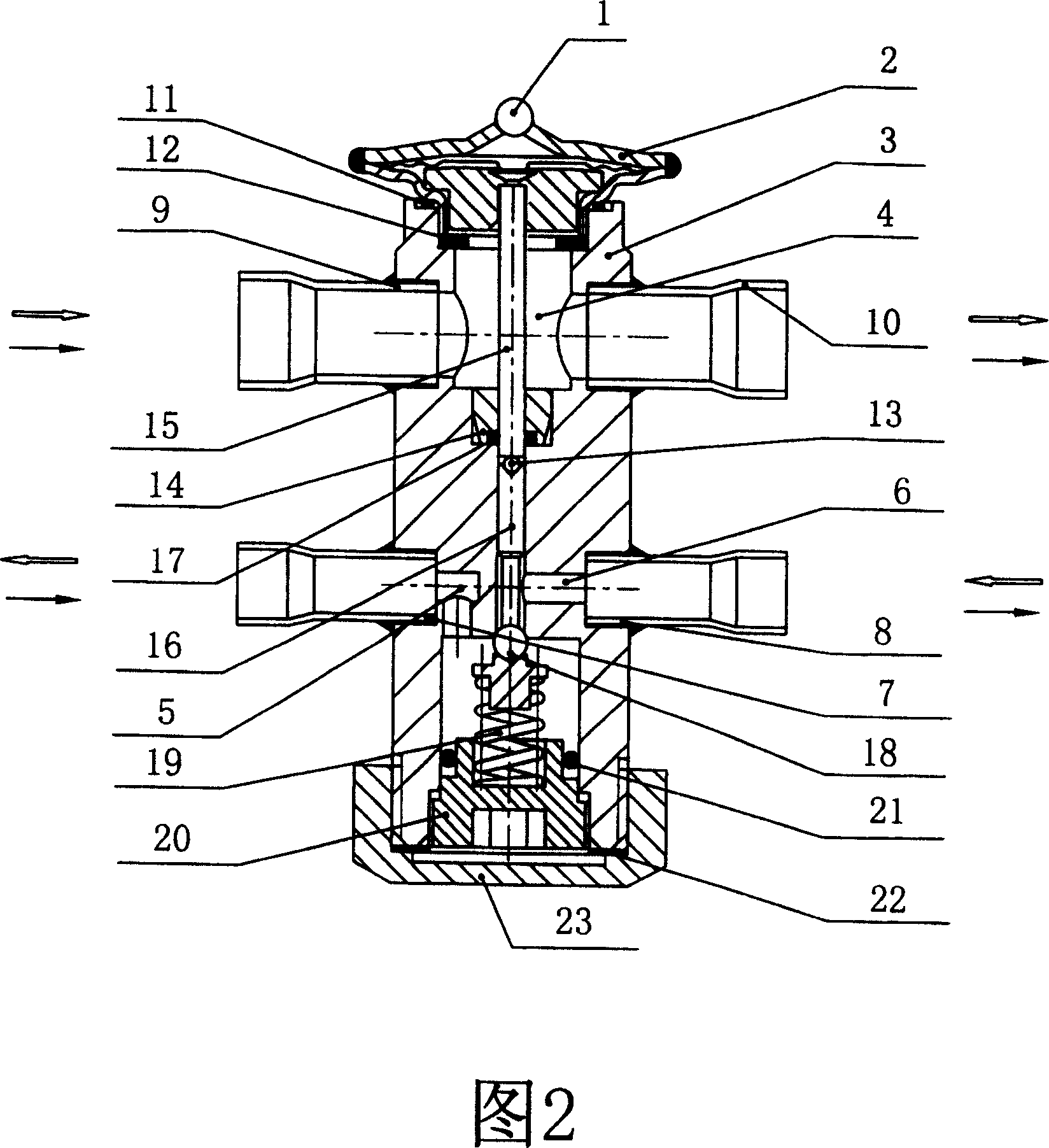
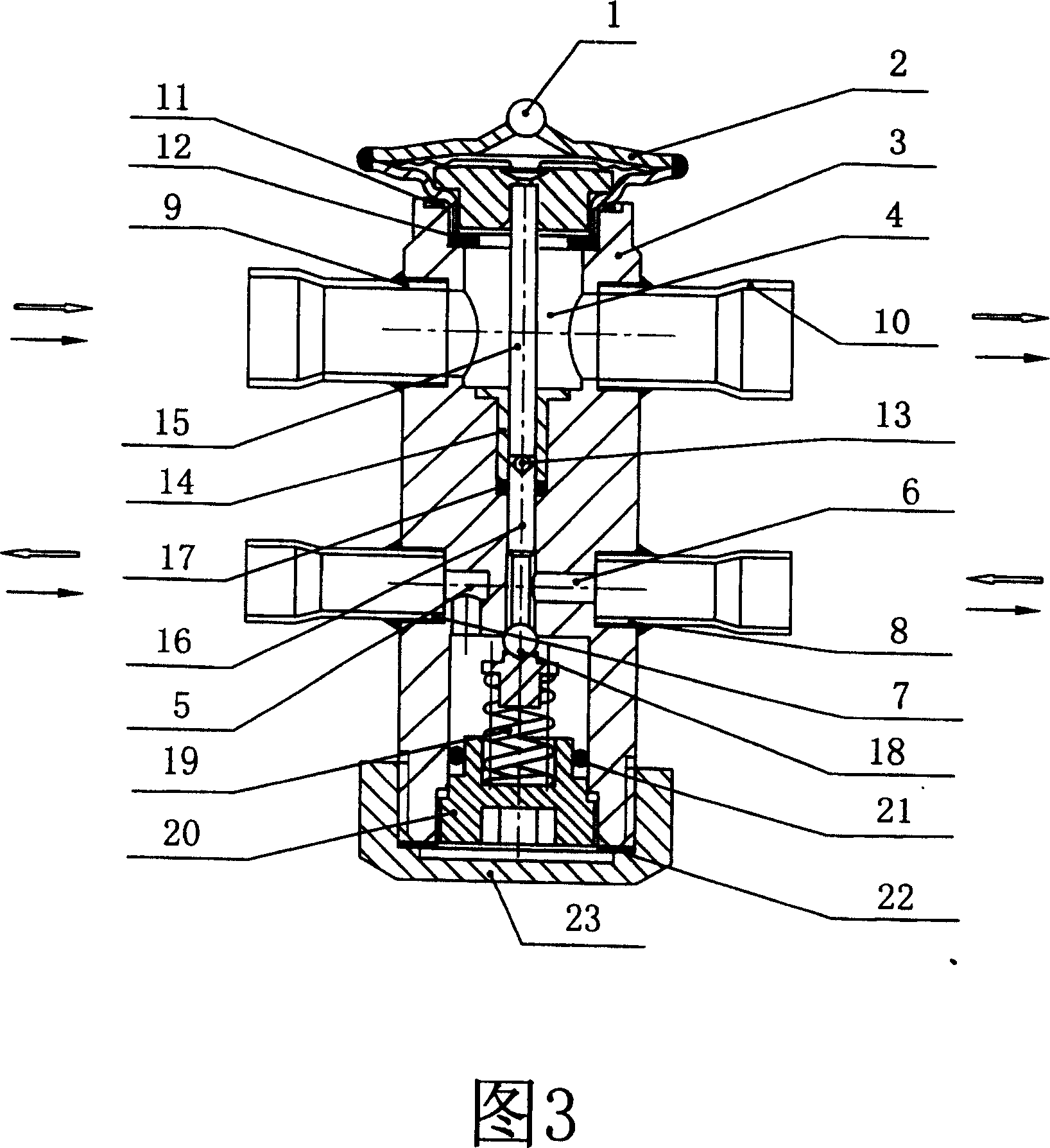
[0021] The present invention mainly consists of a valve body 3 with a membrane box 2 and a gas return passage 4 at the upper end, an air inlet and return pipe 9 and an air return pipe 10 placed at the left and right ends of the air return passage 4, and a liquid inlet pipe 7 placed at the lower part of the valve body 3. The liquid inlet hole 5, the liquid outlet hole 6 with the liquid outlet pipe 8, the valve core 18 placed between the liquid inlet hole 5 and the liquid outlet hole 6, and the balance spring 19 with the adjustment screw 20 placed at the bottom of the valve core 18 , the transmission rod 15, the centering steel ball 13, and the valve needle 16 placed between the bellows 2 and the valve core 18, the positioning block 14 with the rubber sealing ring 17 of the balance part embedded in the bottom of the return air passage 4 of the valve body 3 , The seal nut 23 placed at the bottom of the valve body 3 etc. constitutes.

[0022] Accompanying drawing 1, 2, 3, 4, 5, 6 ...


PUM


Abstract

The bi-directional thermal expansion valve belongs to the field of vapor compressing heat pump system throttle device technology. The bi-directional thermal expansion valve consists of valve body with upper diaphragm box and gas backing passage, gas backing inlet pipe and gas backing outlet pipe separately on two ends of the gas backing passage, liquid inlet pipe below the valve body, liquid outlet pipe, valve core between the liquid inlet pipe and the liquid outlet pipe, balancing spring with regulating screw, transferring rod, positioning steel ball and valve needle set between the diaphragm box and the valve core, positioning block with balancing rubber ring, sealing nut, and other parts. The present invention has reasonable design, simple structure, bi-directional operation, reliable temperature sensing, high regulating sensitivity and high sealing performance.

Description

technical field [0001] The invention relates to a two-way thermal expansion valve, which belongs to the technical field of throttling devices for vapor compression heat pump systems. Background technique [0002] The throttling device in the existing vapor compression heat pump system mainly has the following three structural forms, and has the following defects: [0003] 1. It consists of an electronic expansion valve, a digital computing circuit board and several sensors. Its disadvantages are high cost and high failure rate. [0004] 2. In the small-capacity vapor compression heat pump system, that is, the room air conditioner, two capillary tubes, a tee and a one-way valve are used to form a throttling device. Although it has the advantages of simple structure, reliability, and low cost, it is only used in the only It can only operate economically when it works in a design condition. When it operates in a non-design condition, the cooling (heat) amo...

Claims


Application Information

Patent Timeline
Patent Type & Authority Patents(China)
IPC IPC(8): F16K1/14F16K31/64F16K41/02
Inventor 邓永林顾其江
Why Eureka
Try Eureka