Circuit for parallel operation of Doherty amplifiers

a technology of parallel operation and amplifier, which is applied in the direction of amplifiers, amplifiers with coupling networks, amplifiers with semiconductor devices/discharge tubes, etc., can solve the problems of large signal transmission loss, amplifier to be used at a low efficiency, and suffer from foregoing prior art example, so as to prevent a narrow band and reduce transmission loss

Inactive Publication Date: 2006-03-02
NEC CORP
View PDF20 Cites 48 Cited by
  • Summary
  • Abstract
  • Description
  • Claims
  • Application Information

AI Technical Summary

Benefits of technology

[0019] It is an object of the present invention to provide a compact and low-cost circuit for operating Doherty amplifiers in parallel, which reduces transmission loss, prevent a band from being narrowed.

Problems solved by technology

This situation (i.e. amplifier barely operates near a saturated output) forces the amplifier to be used at a low efficiency.
However, the foregoing prior art example suffers from the following problems.
The conventional combiner circuit illustrated in FIG. 1, presents a problem of larger signal transmission loss and lower amplifier efficiency due to the extended transmission line from each Doherty amplifier to the output.
Further, since the impedance conversion lines and power combiner such as the hybrid circuit are both constructed by one-quarter wavelength transmission lines, the band is limited so that a desired operation can only be performed in a limited narrow band.
Thus, such a configuration is disadvantageous in point of a reduction in size and cost because the line portion including the impedance conversion line is large.

Method used


Image

  • Circuit for parallel operation of Doherty amplifiers
  • Circuit for parallel operation of Doherty amplifiers
  • Circuit for parallel operation of Doherty amplifiers

Examples


Embodiment Construction

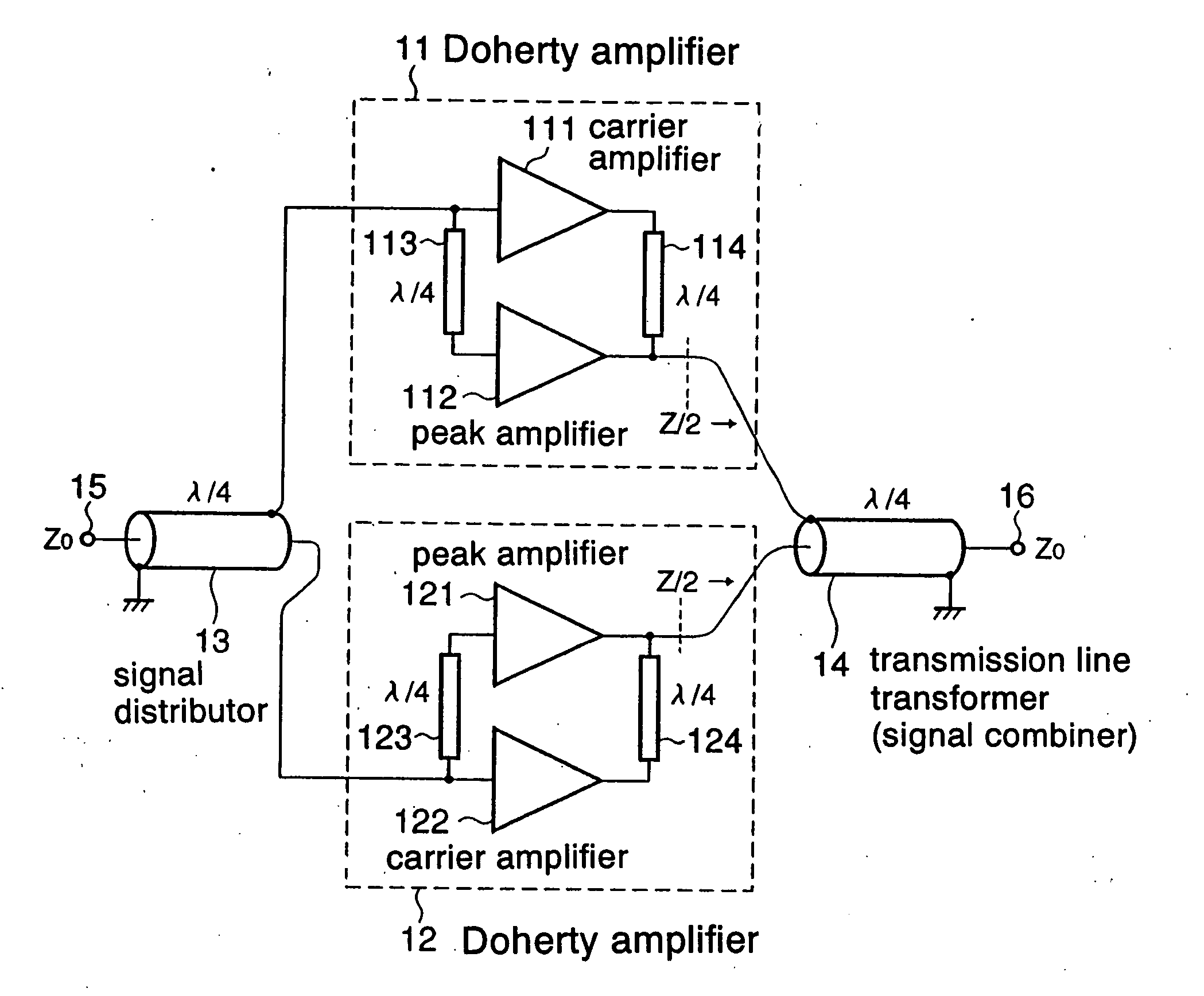
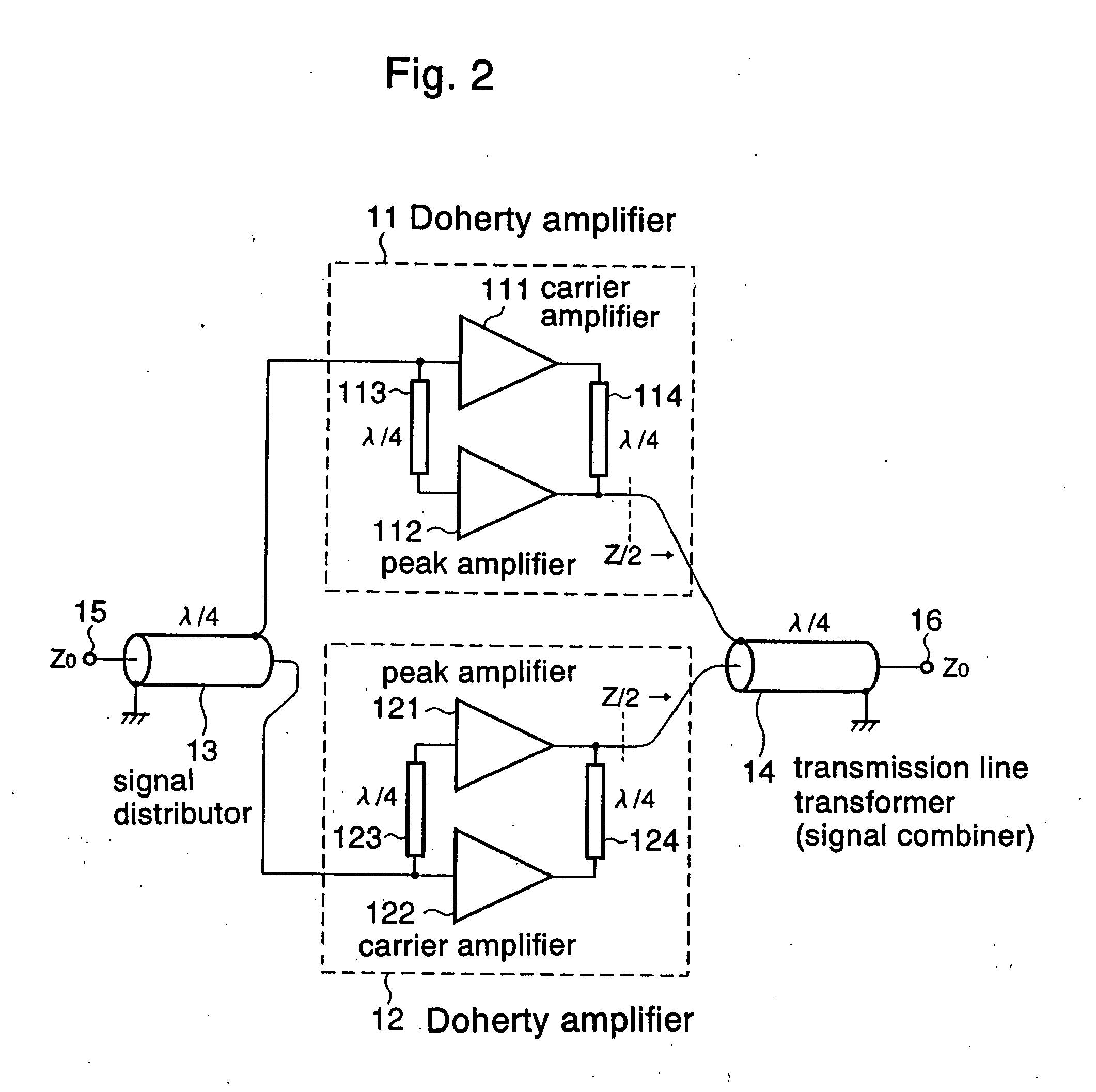
[0028]FIG. 2 is a diagram illustrating the configuration of a Doherty amplifier parallel operation circuit according to one embodiment of the present invention.

[0029] As shown in FIG. 2, the Doherty amplifier parallel operation circuit of this embodiment comprises two Doherty amplifiers 11, 12, signal distributor 13, and transmission line transformer 14. Signal distributor 13 distributes an input signal from input terminal 15 to two Doherty amplifiers 11, 12. Doherty amplifier 11 includes carrier amplifier 111, peak amplifier 112, branch circuit 113, and combiner circuit 114. Similarly, Doherty amplifier 12 comprises carrier amplifier 121, peak amplifier 122, branch circuit 123, and combiner circuit 124. By way of example, branch circuits 113, 123 and combiner circuits 114, 124 are each constituted by a one-quarter wavelength transmission line.

[0030] Outputs of two Doherty amplifiers 11, 12 are combined by transmission line transformer 14, and delivered from output terminal 16 to ...


PUM


Abstract

A circuit is disclosed for operating Doherty amplifiers in parallel in a small size circuit and at a low cost while reducing transmission loss and preventing a narrowed band. The circuit has a plurality of Doherty amplifiers and a signal combiner. Each of the plurality of Doherty amplifiers is applied with a distributed input signal which is amplified and delivered by the Doherty amplifier. The signal combiner is made up of a transmission line transformer, is connected to the outputs of the Doherty amplifiers and to its output terminal. The signal combiner has an impedance as viewed from the Doherty amplifiers, which represents an optimal load for the Doherty amplifiers, and an impedance as viewed from the output terminal, which is equal to the characteristic impedance of a transmission line connected to the output terminal. The signal combiner combines the outputs of the Doherty amplifiers and delivers the resulting output from the output terminal.

Description

BACKGROUND OF THE INVENTION [0001] 1. Field of the Invention [0002] The present invention relates to a Doherty amplifier which combines outputs of a carrier amplifier and a peak amplifier that are different in operation class from each other, to deliver the combined output. [0003] 2. Description of the Related Art [0004] Power amplifiers utilized in radio communications systems are required to provide linearity and high efficiency. [0005] Also, in recent communications systems which employ multi-value digital modulation, often handle signals having a signal amplitude whose average value is different from a maximum value of the same. For amplifying such a signal, in a conventional amplifier, an operating point of the amplifier must be set such that the signal can be amplified without distortions up to a maximum amplitude. For this reason, the amplifier fails to operate near a saturated output, which would allow the amplifier to maintain a relatively high efficiency. This situation (i...

Claims


Application Information

Patent Timeline
Patent Type & Authority Applications(United States)
IPC IPC(8): H03F3/68H03FH03F1/02H03F3/60H03H
CPCH03F3/602H03F1/0288H03F1/07H03F3/68
Inventor SHIIKUMA, KAZUMI
Owner NEC CORP
Why Eureka
Try Eureka