Angle of position object location system and method

a technology of object location and angle, applied in the field of object location systems, can solve the problems of preventing application adoption, affecting the accuracy and reliability of previous attempts to create such a system, and exceedingly complex battery powered devices with high per-unit cost and limited battery life, etc., and achieves efficient object location and tracking.

Active Publication Date: 2006-03-02
SYMBOL TECH LLC
View PDF10 Cites 131 Cited by
  • Summary
  • Abstract
  • Description
  • Claims
  • Application Information

AI Technical Summary

Benefits of technology

[0007] In all of these cases, the system and method is able to determine which of a plurality of zones an object is located in. As one particular application, the system and method can be implemented to determine which of a plurality of portals an object is in, or passing through. In this application, each portal is a defined zone and the system and method can use angle of position and / or distance measurements to determine which portal the object has passed through. Such a system has application in inventory tracking where it is desirable to provide an accurate determination of where a product has been moved to. For example, such a system can be used to confirm that a particular shipment of products have been loaded onto a particular truck through a particular portal. Thus, the system and method can be used to provide efficient object location and tracking.

Problems solved by technology

Unfortunately, previous attempts creating such a system have failed to provide the accuracy and reliability desirable for such a system.
For example, previous systems have relied upon exceedingly complex battery powered devices with high per-unit costs and limited battery life.
The cost and accuracy limitations of these previous methods have prevented their adoption in applications that needed to provide the ability to track and locate large numbers of objects at a relatively low per-unit cost.

Method used


Image

  • Angle of position object location system and method
  • Angle of position object location system and method
  • Angle of position object location system and method

Examples


Embodiment Construction

[0017] The following detailed description is merely exemplary in nature and is not intended to limit the invention or the application and uses of the invention. Furthermore, there is no intention to be bound by any expressed or implied theory presented in the preceding technical field, background, brief summary or the following detailed description

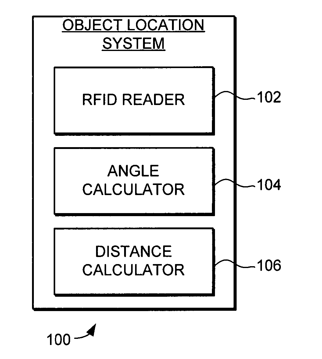
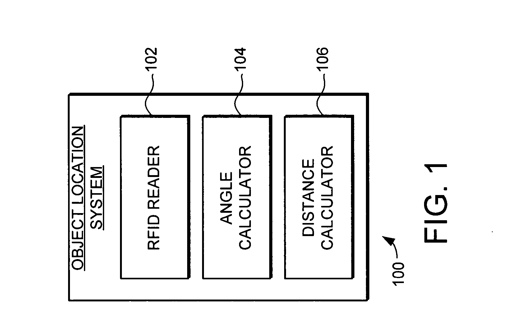
[0018] Generally, the present invention provides a system and method for locating objects that uses Radio Frequency Identification (RFID) tags for more accurate object location. RFID is a technology that incorporates the use of electromagnetic, electrostatic or magnetic coupling in the radio frequency spectrum to identify objects to which RFID tags are affixed. RFID systems in general provide the advantage of not requiring direct contact or line-of-sight scanning. A typical RFID system includes an RFID reader and a plurality of RFID tags that are affixed to the objects of interest. The RFID reader includes an antenna and also includes or ...


PUM


Abstract

An object location system and method is provided for locating objects. The system includes an RFID reader, an angle calculator, and a distance calculator to determine which of a plurality of zones an object is located in or passing through. An RFID tag is affixed with the object that is to be located. The RFID reader transmits signals to the RFID tag and receives backscatter-modulated signals from the RFID tag at one or more RFID antennas. From those received signals, the angle calculator determines an angle of position of the RFID tag relative to the RFID antenna. From the angle of position the zone in which the object is located is determined.

Description

FIELD OF THE INVENTION [0001] This invention generally relates to object location systems, and more specifically relates to object location systems and radio frequency identification (RFID). BACKGROUND OF THE INVENTION [0002] In modem supply management systems there is a growing need for the ability to locate and track a wide variety of objects. This can include the locating and tracking of objects over wide areas, such as large factories and distribution centers. [0003] Unfortunately, previous attempts creating such a system have failed to provide the accuracy and reliability desirable for such a system. For example, previous systems have relied upon exceedingly complex battery powered devices with high per-unit costs and limited battery life. The cost and accuracy limitations of these previous methods have prevented their adoption in applications that needed to provide the ability to track and locate large numbers of objects at a relatively low per-unit cost. [0004] Accordingly, i...

Claims


Application Information

Patent Timeline
Patent Type & Authority Applications(United States)
IPC IPC(8): G08B21/00G01S13/08G08B13/14G08B5/22
CPCG01S3/32G01S5/04G01V15/00G01S13/825G01S13/84G01S5/12
Inventor KNOX, MICHAELBRIDGELALL, RAJDURON, MARK WILLIAMKNADLE, RICHARD T. JR.BENDER, JAMES JOSEPH
Owner SYMBOL TECH LLC
Why Eureka
Try Eureka