Liquid crystal display device and electronic apparatus

a display device and liquid crystal technology, applied in static indicating devices, non-linear optics, instruments, etc., can solve the problems of deteriorating visibility of an observer in reflection mode, difficulty for users to view displayed characters and the like on display units in a dark place, lack of versatility, etc., to achieve the effect of improving visibility

Active Publication Date: 2006-03-02
BOE TECH GRP CO LTD
View PDF7 Cites 53 Cited by
  • Summary
  • Abstract
  • Description
  • Claims
  • Application Information

AI Technical Summary

Benefits of technology

[0014] An advantage of the invention is that it provides a liquid crystal display device with improved visibility, which is capable of distinguishing boundaries between pixels displaying different color images in both a transmission mode and a reflection mode, and an electronic apparatus having the liquid crystal display device.
[0015] According to one aspect of the invention, a liquid crystal display device includes a pair of substrates composed of a first substrate and a second substrate, which are opposite to each other with a liquid crystal layer interposed therebetween, a plurality of pixels arranged in a matrix, reflective layers provided on the second substrate and reflecting incident light from the first substrate side, a plurality of sub-pixels constituting each of the plurality of pixels, color filters on which colored layers having different colors are arranged, each of the colored layers corresponding to each of the sub-pixels, and an illumination unit provided at an outer surface side of the second substrate, the liquid crystal display device being a transflective liquid crystal display device for displaying images through a reflective region and a transmissive region, which are provided in each of the sub-pixels. The reflective region of each sub-pixel is a region for black and white display or monochrome gray scale display, the transmissive region is a region for color image display in the pixels, and the reflectance of the reflective region of each sub-pixel is different for each of the sub-pixels having different colors.
[0016] The liquid crystal display device provides a transflective liquid crystal display device for performing color display in a transmission display mode and black and white display or monochrome gray scale display in a reflection display mode. In the liquid crystal display device, a sub-pixel is a pixel of the minimum unit for driving the liquid crystal individually and corresponds to a region in which a pair of electrodes are opposite to each other with a liquid crystal layer interposed therebetween. In addition, a pixel (dot), which is the minimum unit of display of an image, is formed by a plurality of sub-pixels having different colors. In addition, the sub-pixel is prepared to correspond to two pixel electrodes and, for example, is formed in an overlapping portion of a pixel electrode provided on one of a pair of substrates and a pixel electrode provided on the other of the pair of substrates.
[0017] Conventionally, the reflectance of the reflective regions provided for the sub-pixels having different colors is equal for all sub-pixels. That is, incident light from a first substrate is reflected in all sub-pixels having different colors with the same reflectance and the reflected light is viewed by an observer at the first substrate side.
[0018] In such a case, for example, in the transmission display mode, it is assumed that each pixel among adjacent pixels displays an image through one of the sub-pixels having different colors. In the transmission display mode, since each pixel displays the image through each of the sub-pixels having different colors, there occurs a color difference and / or a brightness difference between adjacent pixels, so that the observer can distinguish a boundary between the adjacent pixels.
[0019] Here, for example, considering the black and white display, since colored layers are not present in the reflective regions, the black and white display is obtained in the reflection display mode. Accordingly, when each of the adjacent pixels displays the image through one of the sub-pixels having different colors, the reflective regions provided in the sub-pixels of each pixel have the same reflectance, and thus the amount of the reflected light emitted from the adjacent pixels becomes equal. Accordingly, since the brightness difference as well as the color difference between the adjacent pixels is not present, the observer cannot distinguish the boundary between the adjacent pixels.

Problems solved by technology

However, since the reflection-type liquid crystal display devices display images using external light such as natural light, for example, sunlight or illumination light, there is a problem in that it is difficult for users to view displayed characters and the like on display units in a dark place.
For example, in the case of a liquid crystal display device for use in a portable telephone, there is a problem in the lack of versatility, as in the case in which the black and white display can be performed in a standby mode (reflection display when the backlight is turned off) and the color display can be performed in an operation mode (transmission display when the backlight is turned on).
As a result, no difference occurs in brightness at a boundary between the background image and the character images, and accordingly, it is difficult to distinguish the boundary between the background image and the character images, which results in deterioration of visibility for an observer in the reflection mode.

Method used


Image

  • Liquid crystal display device and electronic apparatus
  • Liquid crystal display device and electronic apparatus
  • Liquid crystal display device and electronic apparatus

Examples


first embodiment

[0053] Now, a first embodiment of the invention will be described with reference to the drawings.

Electro-Optical Device

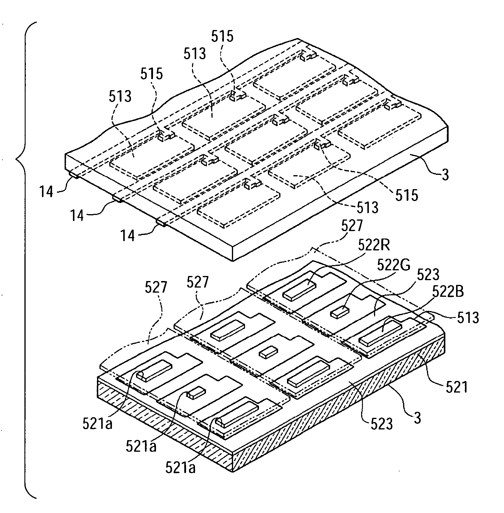
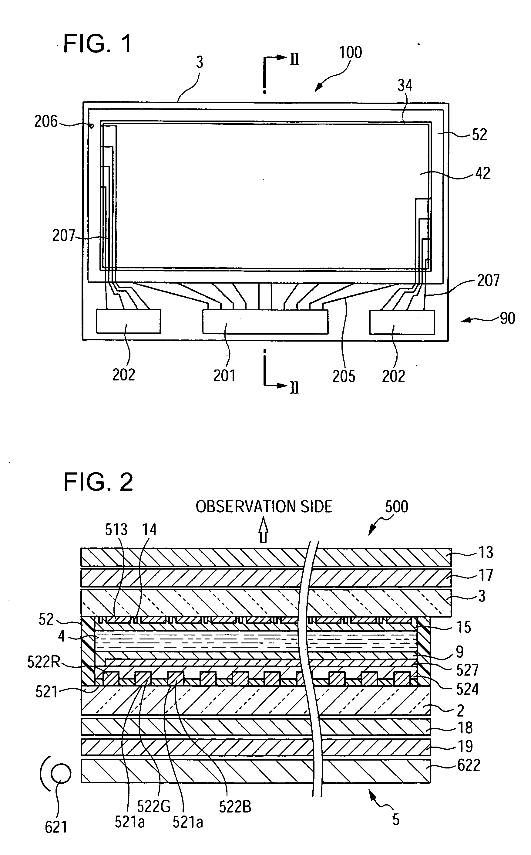
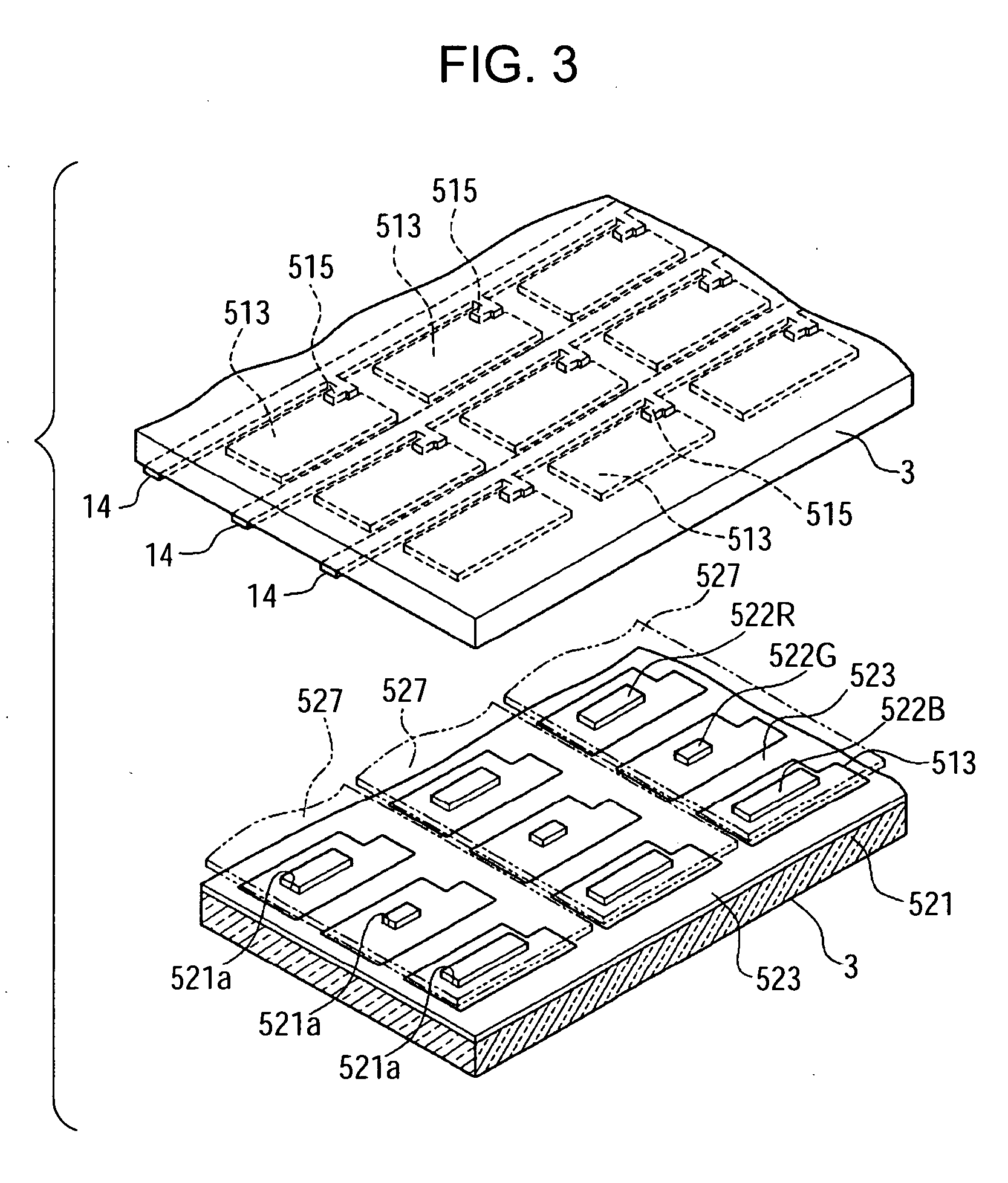
[0054]FIG. 1 is a plan view schematically illustrating the structure of a liquid crystal display device according to the first embodiment of the invention. The electro-optical device according to this embodiment is a transflective electro-optical device including a transmissive display mode in which incident light from a backlight (not shown) is transmitted to display images and a reflective display mode in which incident light from an observer side is reflected to display images. In addition, this embodiment employs an active-matrix-type liquid crystal display device using thin Film diodes (TFDs), which are non-linear elements of a two-terminal type, as switching elements.

[0055] As shown in FIG. 1, a liquid crystal display device 100 according to this embodiment includes a pair of a first substrate 3 and a second substrate 2 (not shown in FIG. 1) bonded by mean...

second embodiment

[0102] Next, a liquid crystal display device according to a second embodiment of the invention will be described with reference to the drawings.

[0103] The liquid crystal display device according to the second embodiment is different from that of the first embodiment in that the reflectance of the reflective layers 521 of the sub-pixels 551R, 551G, and 551B becomes different for the respective sub-pixel 551R, 551G, and 551B by changing an area of the black matrix 523 partitioning the sub-pixels 551. Except for this difference, the liquid crystal display device of the second embodiment has the same basic configuration as that of the first embodiment. In the second embodiment, the same elements as the first embodiment are denoted by the same reference numerals, and the description thereof will be omitted.

[0104]FIG. 6 is a plan view of a plurality of sub-pixels 551 arranged in a matrix on the second substrate 2.

[0105] As shown in FIG. 6, the sub-pixels 551R, 551G, and 551B are regula...

third embodiment

[0110] Next, a liquid crystal display device according to a third embodiment of the invention will be described with reference to the drawings.

[0111] The liquid crystal display device according to the third embodiment is different from that of the first embodiment in that the reflectance of the reflective layers 521 of the sub-pixels 551R, 551G, and 551B becomes different for each of the sub-pixels R, G and B by forming unevenness on the reflective layers 521 corresponding to the sub-pixels 551R, 551G, and 551B. Except for this difference, the liquid crystal display device of the third embodiment has the same basic configuration as that of the first embodiment. In the third embodiment, the same elements as the first embodiment are denoted by the same reference numerals, and the description thereof will be omitted.

[0112]FIG. 7 is a cross-sectional view of a plurality of sub-pixels 551 arranged in a matrix on the second substrate 2.

[0113] As shown in FIG. 7, the reflective regions ...


PUM


Abstract

A liquid crystal display device includes a pair of substrates composed of a first substrate and a second substrate, which are disposed opposite to each other with a liquid crystal layer interposed therebetween; a plurality of pixels arranged in a matrix; reflective layers that are provided on the second substrate and reflects incident light from the first substrate side; a plurality of sub-pixels constituting each of the plurality of pixels; color filters on which colored layers having different colors are arranged, each of the colored layers corresponding to each of the sub-pixels; and an illumination unit provided at an outer surface side of the second substrate. The liquid crystal display device is a transflective liquid crystal display device for displaying images through a reflective region and a transmissive region, which are provided in each of the sub-pixels. The reflective region of each sub-pixel is a region for black and white display or monochrome gray-scale display, the transmissive region is a region for color display in the pixels, and reflectance of the reflective region of each sub-pixel is different for each of the sub-pixels having different colors.

Description

BACKGROUND OF THE INVENTION [0001] 1. Technical Field [0002] The present invention relates to a liquid crystal display device and to an electronic apparatus. [0003] 2. Related Art [0004] Reflection-type liquid crystal display devices, which have an advantage of low power consumption because of not having a light source, such as a backlight and the like, have been generally employed for additional display units to various portable electronic apparatuses and the like. However, since the reflection-type liquid crystal display devices display images using external light such as natural light, for example, sunlight or illumination light, there is a problem in that it is difficult for users to view displayed characters and the like on display units in a dark place. [0005] In order to overcome such a disadvantage, a liquid crystal display device has been widely used to allow images to be viewed by observers using the external light in a light place like the general reflection-type liquid c...

Claims


Application Information

Patent Timeline
Patent Type & Authority Applications(United States)
IPC IPC(8): G09G3/36
CPCG02F1/133514G02F1/133555G09G2300/0456G09G3/367G09G2300/0439G02F1/1365G02F1/1335
Inventor TAKIZAWA, KEIJIKATO, TATSUYA
Owner BOE TECH GRP CO LTD
Why Eureka
Try Eureka