Multilayer ceramic condenser

a ceramic condenser and multi-layer technology, applied in the direction of multiple fixed capacitors, fixed capacitor details, capacitors, etc., can solve the problems of difficult to achieve a smaller size/lower profile and a larger capacity of multi-layer ceramic condensers, and achieve a smaller size/lower profile and a lower profile. , the effect of enhancing

Active Publication Date: 2006-03-02
TDK CORPARATION
View PDF3 Cites 4 Cited by
  • Summary
  • Abstract
  • Description
  • Claims
  • Application Information

AI Technical Summary

Benefits of technology

[0012] In the present invention, the number of capacitors formed in an inner electrode group positioned on the inner side of the outermost inner electrode group is smaller than the number of capacitors formed in the outermost inner electrode group. As a consequence, the combined capacitance of the capacitors formed in the inner electrode group positioned on the inner side of the outermost inner electrode group is greater than the combined capacitance of the capacitors formed in the outermost inner electrode group. When the number of capacitors formed in the outermost inner electrode group is made different from the number of capacitors formed in the inner electrode group positioned on the inner side, the combined capacitance of the whole ceramic condenser can be enhanced. As a result, the present invention can attain a smaller size and a lower profile than those simply increasing the number of inner electrode groups in order to secure a desirable capacitance.
[0013] In the present invention, the number of capacitors formed in the outermost inner electrode group in the laminating direction of the multilayer body is greater than the number of capacitors formed in the inner electrode group positioned on the inner side of the outermost inner electrode group. This weakens the electric field formed on the outside of the ceramic condenser, whereby the surface flashover voltage can be kept high.

Problems solved by technology

HEI 8-37126 can attain a higher withstand voltage and raise the surface flashover voltage, but is hard to achieve a smaller size / lower profile and a larger capacity.
Though the number of inner electrode groups provided within the multilayer body may be increased so as to secure a desirable capacitance, this makes it difficult for the multilayer ceramic condenser to attain a smaller size and a lower profile.
Though the thickness of the outer layer part not formed with the inner electrodes may be increased so as to raise the surface flashover voltage, the multilayer ceramic condenser is less likely to achieve a smaller size and a lower profile as the outer layer part becomes thicker.

Method used


Image

  • Multilayer ceramic condenser
  • Multilayer ceramic condenser
  • Multilayer ceramic condenser

Examples


Embodiment Construction

[0025] In the following, preferred embodiments of the present invention will be explained in detail with reference to the accompanying drawings. In the explanation, constituents identical to each other or those having the same functions will be referred to with numerals identical to each other without repeating their overlapping descriptions.

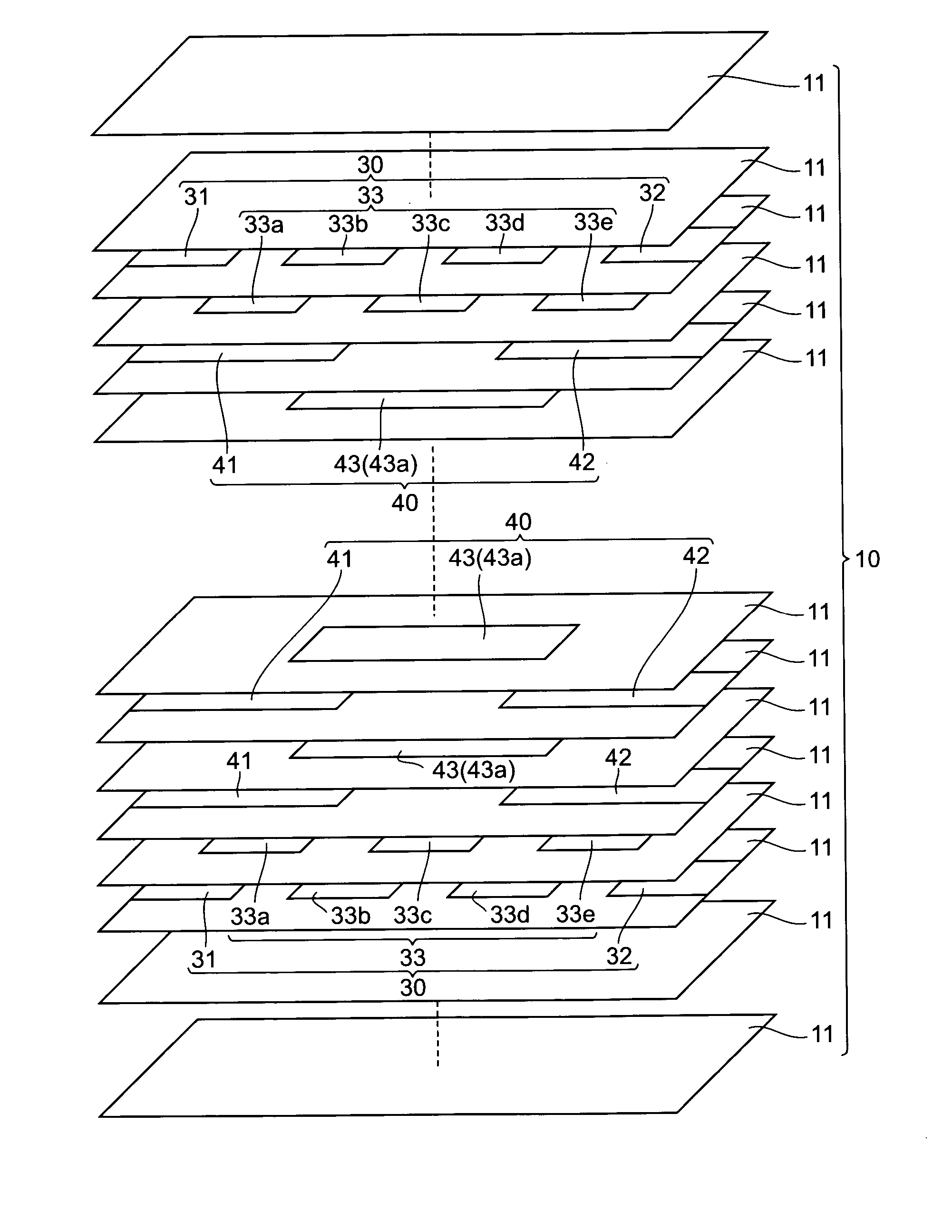
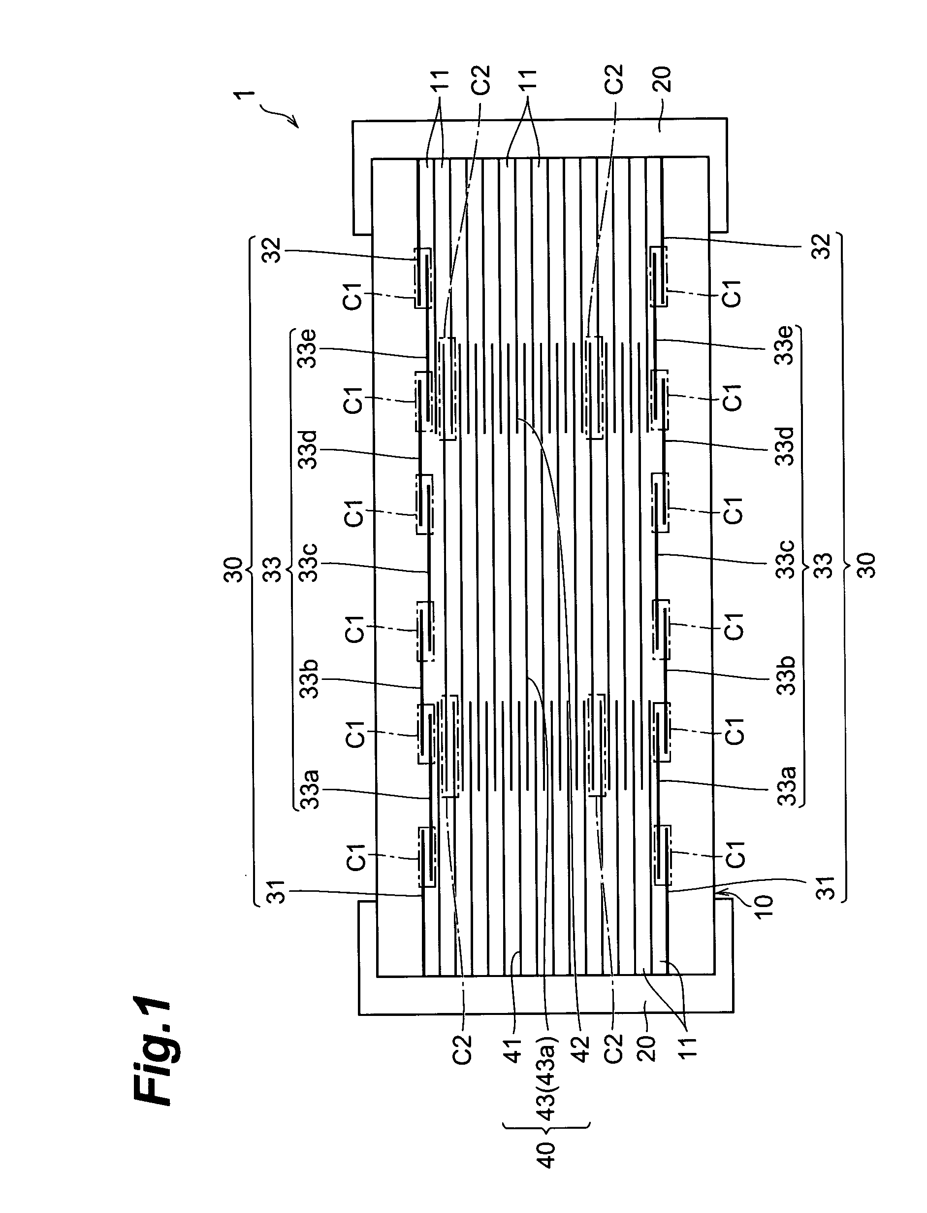
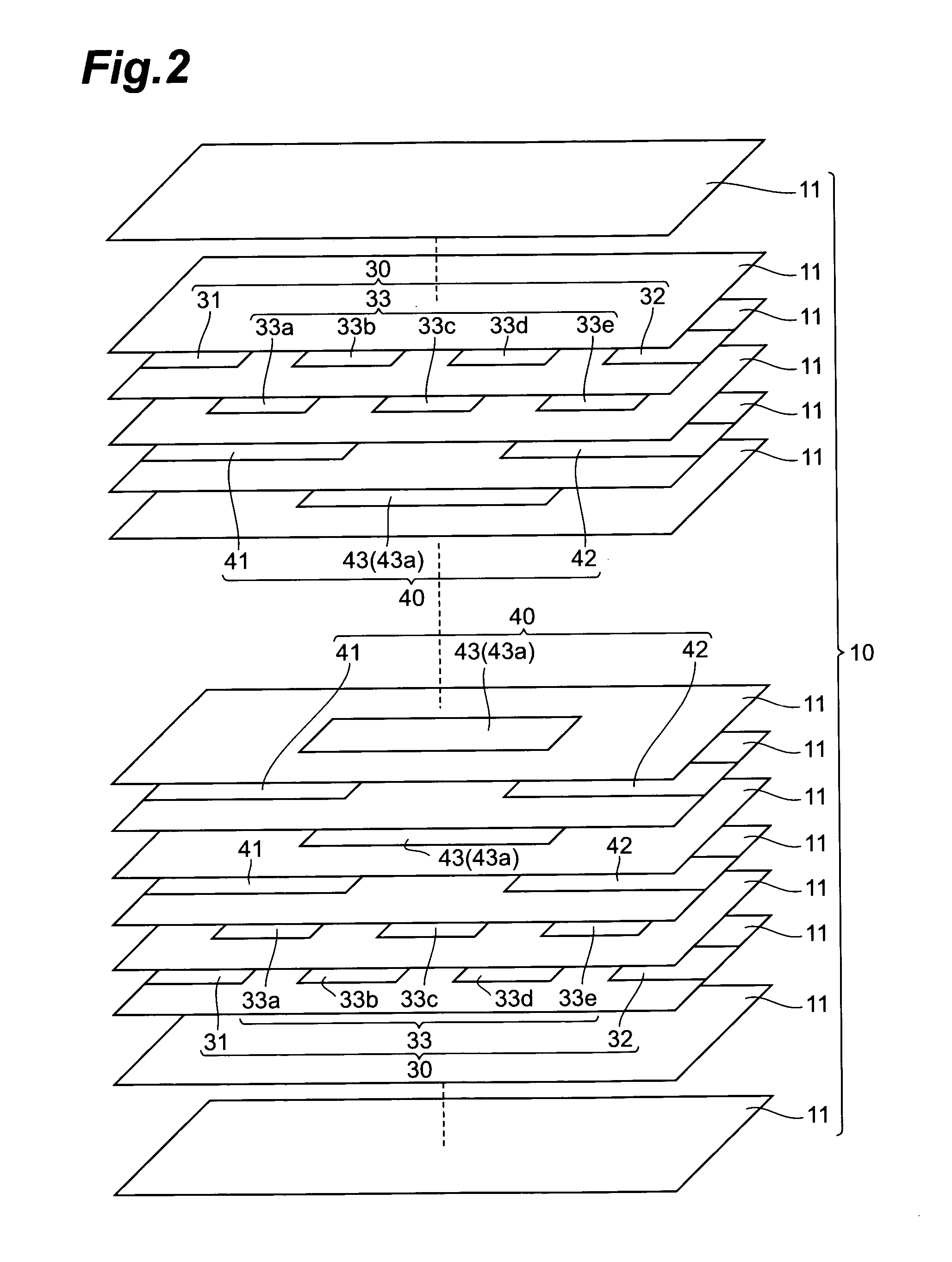
[0026] First, the configuration of a multilayer ceramic condenser 1 in accordance with an embodiment will be explained with reference to FIGS. 1 and 2. FIG. 1 is a view illustrating a cross-sectional configuration of the multilayer ceramic condenser in accordance with this embodiment. FIG. 2 is an exploded perspective view for explaining the configuration of the multilayer ceramic condenser in accordance with this embodiment. FIG. 2 does not show terminal electrodes 20 which will be explained later.

[0027] The multilayer ceramic condenser 1 comprises a multilayer body 10; a first terminal electrode 20a, a second terminal electrode 20b; first in...


PUM

PropertyMeasurementUnit
surface flashover voltageaaaaaaaaaa
voltageaaaaaaaaaa

Abstract

A multilayer ceramic condenser comprises a multilayer body constituted by a plurality of dielectric layers laminated together, first and second terminal electrodes respectively positioned on opposite side faces of the multilayer body, and a plurality of inner electrode groups provided within the multilayer body in a laminating direction of the multilayer body. Each inner electrode group includes a first inner electrode connected to the first terminal electrode, a second inner electrode connected to the second terminal electrode, and a third inner electrode connected to none of the first and second terminal electrodes. The first, second, and third inner electrodes are arranged so as to hold the dielectric layer therebetween such that a plurality of capacitors connected in series are formed between the first and second inner electrodes. The number of capacitors formed in the outermost inner electrode group in the laminating direction of the multilayer body is greater than the number of capacitors formed in the inner electrode group positioned on the inner side of the outermost inner electrode group.

Description

BACKGROUND OF THE INVENTION [0001] 1. Field of the Invention [0002] The present invention relates to a multilayer ceramic condenser. [0003] 2. Related Background Art [0004] Known as this kind of multilayer ceramic condenser is one comprising a multilayer body constituted by a plurality of dielectric layers laminated together, first and second terminal electrodes respectively positioned on opposite side faces of the multilayer body, and a plurality of inner electrode groups provided within the multilayer body in a laminating direction thereof (see, for example, Japanese Patent Application Laid-Open No. HEI 8-37126). Each inner electrode group includes a first inner electrode connected to the first terminal electrode, a second inner electrode connected to the second terminal electrode, and a third inner electrode connected to none of the first and second terminal electrodes. The first to third inner electrodes are arranged so as to hold the dielectric layer therebetween such that a pl...

Claims


Application Information

Patent Timeline
Patent Type & Authority Applications(United States)
IPC IPC(8): H01G4/005
CPCH01G4/012H01G4/30H01G4/18H01G4/06
Inventor SHIMIZU, MICHIHISAITO, KAZUNORIKOMATSU, TOSHIAKI
Owner TDK CORPARATION
Why Eureka
Try Eureka