Structure of AC light-emitting diode dies

a technology of light-emitting diodes and dies, which is applied in the direction of digital storage, semiconductor/solid-state device details, instruments, etc., can solve the problems of affecting the whole loop formed with the damaged led included, the power level of prior leds is generally limited in acceptable range, and the set of leds in which the damaged led resides is also likely to be damaged, etc., to achieve the effect of broadening the range of effects

Active Publication Date: 2006-03-02
EPISTAR CORP
View PDF10 Cites 100 Cited by
  • Summary
  • Abstract
  • Description
  • Claims
  • Application Information

AI Technical Summary

Benefits of technology

[0012] An object of the invention is therefore to provide a structure of light-emitting diode (LED) dies having an alternating current (AC) loop abbreviated as a structure of AC LED dies, on which an AC power supply may be applied directly to considerably broaden applicable range.

Problems solved by technology

However, prior LEDs are generally limited in their acceptable power levels.
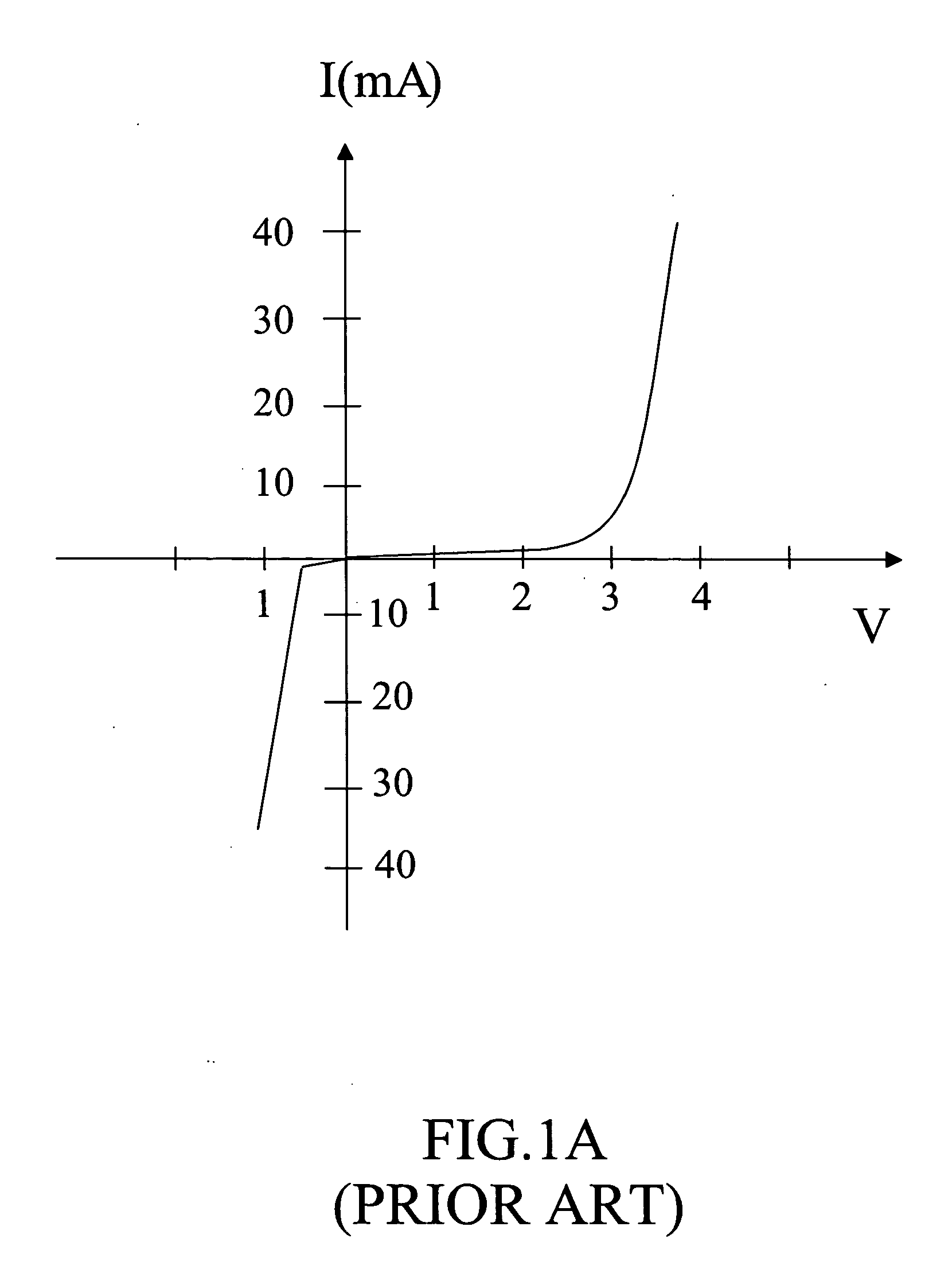
Most LEDs may be fed with only low DC voltages and may be damaged if high voltages or AC voltages are applied thereon.
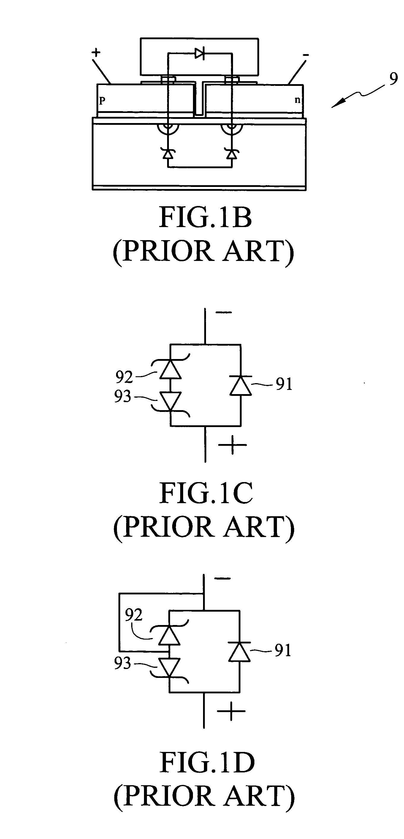
However, once a single LED arranged among the plurality of LEDs is damaged, the set of LEDs in which the damaged LED resides is also likely to become damaged and the whole of the loop formed with the damaged LED included is badly affected.
Unfortunately, the total amount of wires used for these LEDs in a specific application is unavoidably increased and the power consumption increases correspondingly.
Furthermore, the voltage at an end of one of the wires is insufficient and thus causes uneven luminance of the LEDs.
There is another serious problem with a low DC voltage operated ALInGaN LED.
When this occurs, an instantaneous high reverse voltage is burst forth and the LED is damaged.
However, although the problem of high power consumption may be overcome by such circuit assembly schemes, the corresponding large volume of the LED based circuit considerably limits its actual applicable range.
Although such LEDs may be operated with a high voltage, they may still not be applied with an AC voltage.
Although the LEDs may be operated with a high voltage, they also have the problem of not being capable of operation with AC voltage.

Method used


Image

  • Structure of AC light-emitting diode dies
  • Structure of AC light-emitting diode dies
  • Structure of AC light-emitting diode dies

Examples


Embodiment Construction

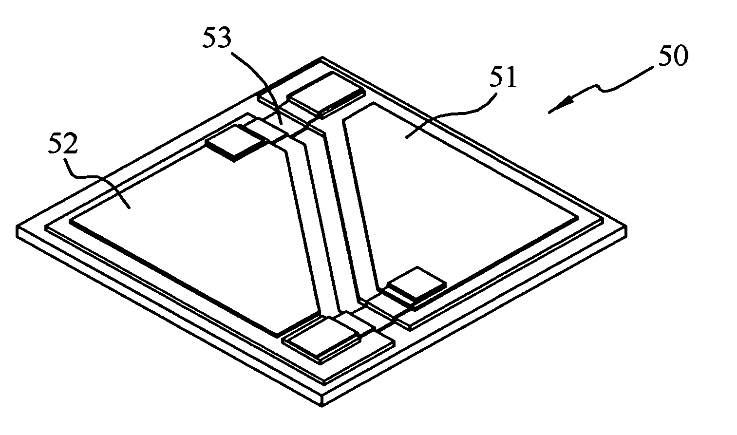
[0032] A structure of light-emitting diode (LED) dies having an alternating current (AC) loop, which may be fed with a direct AC power supply, is disclosed in the invention (abbreviated as a structure of AC LED dies). The structure of AC LED dies comprises at least a unit of AC LED micro-dies 50, which will be described in the following. Referring to FIG. 3, the unit of AC LED micro-dies comprises a first LED micro-die and a second LED micro-die 21 and 22 arranged in mutually reverse orientations and connected in parallel. The unit of AD LED micro-dies has an equivalent circuit as shown in FIG. 4A. Since the first and second LED micro-dies 21 and 22 are oriented reversely and connected in parallel, the first LED micro-die 21 emits light when a positive-half wave voltage in the AC power supply is applied, while the second LED micro-die 22 emits light when a negative-half wave voltage in the AC power supply is applied. Therefore, the unit of LED micro-dies may emit light continuously ...


PUM


Abstract

A structure of light-emitting diode (LED) dies having an AC loop (a structure of AC LED dies), which is formed with at least one unit of AC LED micro-dies disposed on a chip. The unit of AC LED micro-dies comprises two LED micro-dies arranged in mutually reverse orientations and connected with each other in parallel, to which an AC power supply may be applied so that the LED unit may continuously emit light in response to a positive-half wave voltage and a negative-half wave voltage in the AC power supply. Since each AC LED micro-die is operated forwardly, the structure of AC LED dies also provides protection from electrical static charge (ESD) and may operate under a high voltage.

Description

BACKGROUND OF THE INVENTION [0001] 1. Field of Invention [0002] The invention relates to a structure of light-emitting diodes (LED), and particularly to a structure of LED dies with an alternating current (AC) loop (a structure of AC LED dies). [0003] 2. Related Art [0004] A light-emitting diode (LED) emits light based on its semi-conductive characteristics, in contrast to the heating light-emitting principle of a fluorescent lamp, and is thus called a cold light. The LED provides a number of advantages such as high endurance, long lifetime, compactness, low power consumption and so forth. Furthermore, no pernicious material such as mercury is contained in the LED. Therefore, there are high expectations with respect to the LEDs for being a light source in daily life in the current lighting market. [0005] However, prior LEDs are generally limited in their acceptable power levels. Most LEDs may be fed with only low DC voltages and may be damaged if high voltages or AC voltages are app...

Claims


Application Information

Patent Timeline
Patent Type & Authority Applications(United States)
IPC IPC(8): G11C11/00H01L33/08H01L33/32H01L33/38H01L33/62
CPCH01L25/0753H01L2924/0002H01L2924/00
Inventor LIN, MING-TEHWANG, FEI-CHANGKUO, CHIA-TAI
Owner EPISTAR CORP
Why Eureka
Try Eureka