Firewall proxy system and method

a proxy system and firewall technology, applied in the field of real-time media communication, can solve the problems of inability to establish inbound” udp/ip channels, inability to implement compatible modifications to known solutions developed by multiple providers, and inability to call signaling messages los

Active Publication Date: 2006-03-02
INNOMEDIA PTE
View PDF3 Cites 63 Cited by
  • Summary
  • Abstract
  • Description
  • Claims
  • Application Information

AI Technical Summary

Benefits of technology

[0012] A first aspect of the present invention is to provide a media gateway control protocol (MGCP) proxy server for interfacing a plurality of MGCP gateways with a plurality of MGCP call agents independent of whether each of the gateways is served by a network address translation server. Each gateway may be a multi-me

Problems solved by technology

A problem associated with such Internet telephony systems is that network address translation (NAT) firewalls prevent the transmission of UDP/IP frames from an endpoint outside the firewall to an endpoint on a private network inside the firewall.
Therefore, if any of the calling MTA, the callee gateway, or the MGCP call agent are behind a NAT firewall, the call signaling messages will be lost and “inbound” UDP/IP channels can not be established.
One problem with such solutions is that they require modifying known call agent systems such that: i) signaling to the MTA must occur usin

Method used


Image

  • Firewall proxy system and method
  • Firewall proxy system and method
  • Firewall proxy system and method

Examples


first embodiment

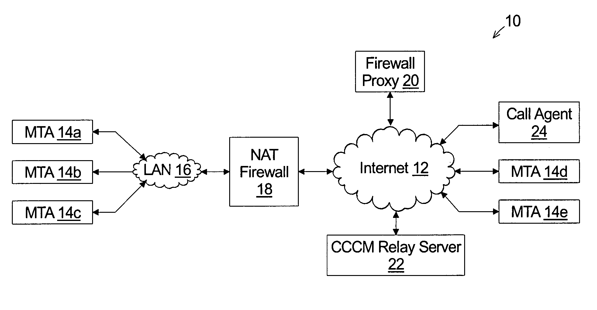
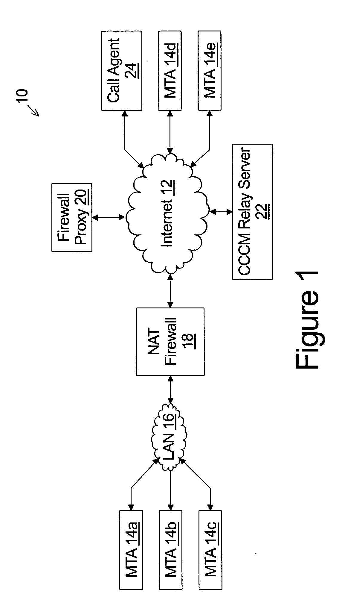
[0093] The ladder diagram of FIG. 6a represents a portion of MGCP signaling which may occur to: i) activate a private network MTA 14a with the call agent 24; and ii) signal a call from an Internet MTA 14d to the private network MTA 14a in the present invention (e.g. FIG. 1) wherein the firewall proxy 20, the call agent 24, and the CCCM relay server 22 are all coupled to the Internet 12.

[0094] To register with the call agent 24, the MTA 14a sends a restart in progress (RSIP) message addressed to a preconfigured IP address at step 65. In a typical MGCP implementation, this IP address would represent the call agent supporting the MTA 14a, however, in this invention, the preconfigured IP address is that of the firewall proxy 20.

[0095] The firewall proxy 20 translates the RSIP message as discussed in more detail with respect to FIG. 17 and forwards the translated RSIP message to the call agent 24 at step 67. As discussed, the firewall proxy 20 emulates an MTA when communicating with the...

second embodiment

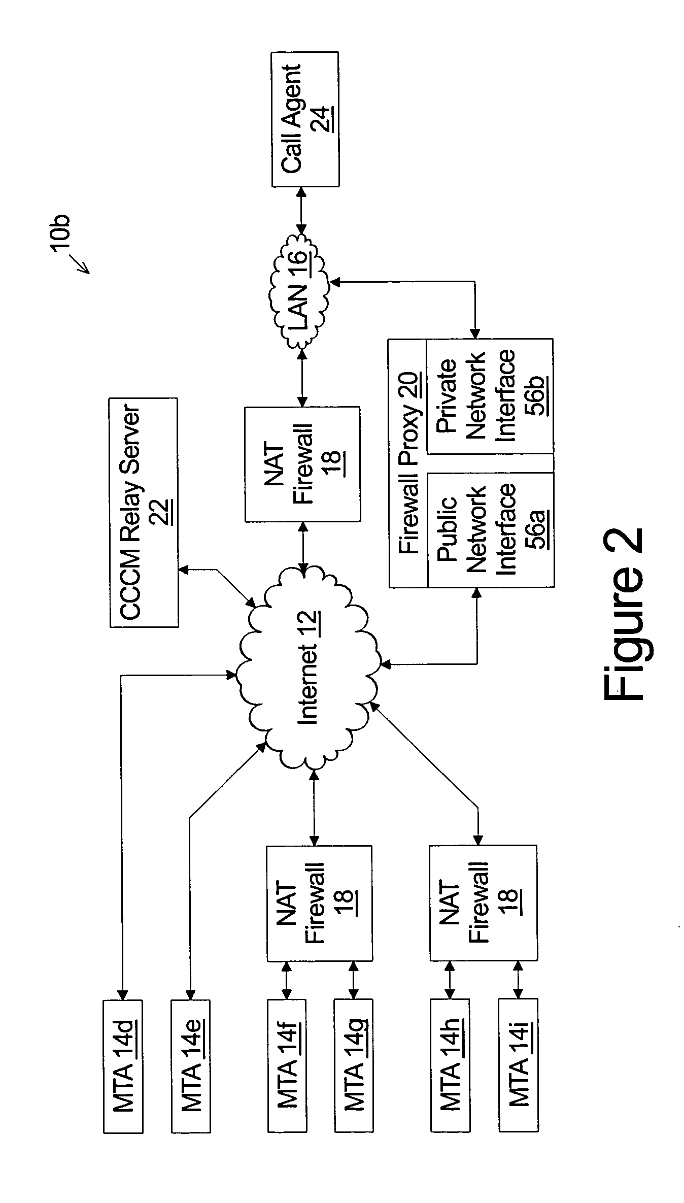
[0109] The ladder diagram of FIG. 6b represents a portion of MGCP signaling which may occur to: i) register each of a private network MTA 14f and a private network MTA 14h with the call agent 24; and ii) signal a call initiated by the private network MTA 14h to the private network MTA 14f in the present invention (e.g. FIG. 2) wherein the call agent 24 is coupled to the local area network 15 and the firewall proxy 20 is coupled to both the local area network 16 and the Internet 12.

[0110] Step 101 represents the MTA 14f sending a restart in progress (RSIP) message addressed to a preconfigured IP address. As discussed, in the typical MGCP implementation, this IP address would represent the call agent supporting the MTA 14f, however, in this invention, the preconfigured IP address is the public IP address assigned to the public network interface 56a of the firewall proxy 20.

[0111] The firewall proxy 20 translates the RSIP message as discussed in more detail with respect to FIG. 17 and...


PUM


Abstract

A media gateway control protocol (MGCP) proxy server interfaces between a plurality of MGCP gateways and at least one MGCP call agent which may be coupled to a private network and served by a network address translation firewall. The proxy server comprises a private network interface for communicating over a private network with the call agent and a public network interface for communicating over the Internet. A translation module provides for receiving an MGCP message generated by a gateway and addressed to the public network interface. The MGCP message includes a message transaction ID assigned by the gateway and an endpoint ID identifying the gateway. The endpoint ID comprises a local endpoint name and a domain. The translation module translating the MGCP message to create a translated message by: i) substituting a unique transaction ID in place of the message transaction ID; and ii) substituting a private IP address assigned to a private network interface in place of the domain of the endpoint ID of the MGCP message. The translation module: i) provides the translated message to the private network interface for sending to the call agent; ii) writes each of the unique transaction ID and the message transaction ID to a record of a gateway request map; and iii) writes the public socket on which the message was received from the gateway to a record associated with the MGCP gateway in a registration map and updates an indication of a predetermined time window during which the public socket is valid to a time period following receipt of the MGCP message.

Description

TECHNICAL FIELD [0001] The present invention relates to real time media communications in a packet switched data network and, more specifically, to establishing and maintaining real time media communication channels through a firewall. BACKGROUND OF THE INVENTION [0002] For many years voice telephone service was implemented over a circuit switched network commonly known as the public switched telephone network (PSTN) and controlled by a local telephone service provider. In such systems, the analog electrical signals representing the conversation are transmitted between the two telephone handsets on a dedicated twisted-pair-copper-wire circuit. More specifically, each telephone handset is coupled to a local switching station on a dedicated pair of copper wires known as a subscriber loop. When a telephone call is placed, the circuit is completed by dynamically coupling each subscriber loop to a dedicated pair of copper wires between the two switching stations. [0003] More recently, th...

Claims


Application Information

Patent Timeline
IPC IPC(8): H04L12/66
CPCH04L29/12009H04L29/12462H04L61/2567H04L61/255H04L29/12509H04L61/00
Inventor WU, JIANMINCHANG, CHEN-HUEI
Owner INNOMEDIA PTE
Why Eureka
Try Eureka