Techniques to reduce latency in receive side processing

a technology of receiving side processing and receiving side, which is applied in the field of receiving side processing to reduce latency, can solve the problems of unfulfilled utilization of network bandwidth, and achieve the effect of reducing the number of receive side processing

Inactive Publication Date: 2006-03-02
INTEL CORP
View PDF4 Cites 29 Cited by
  • Summary
  • Abstract
  • Description
  • Claims
  • Application Information

AI Technical Summary

Problems solved by technology

Advances in network bandwidths, however, have not been fully utilized due to latency that may be associated with processing protocol stacks.
Latency may result from bottlenecks in the computer system from...

Method used


Image

  • Techniques to reduce latency in receive side processing
  • Techniques to reduce latency in receive side processing
  • Techniques to reduce latency in receive side processing

Examples


Embodiment Construction

[0009] Reference throughout this specification to “one embodiment” or “an embodiment” means that a particular feature, structure, or characteristic described in connection with the embodiment is included in at least one embodiment of the present invention. Thus, the appearances of the phrase “in one embodiment” or “an embodiment” in various places throughout this specification are not necessarily all referring to the same embodiment. Furthermore, the particular features, structures, or characteristics may be combined in one or more embodiments.

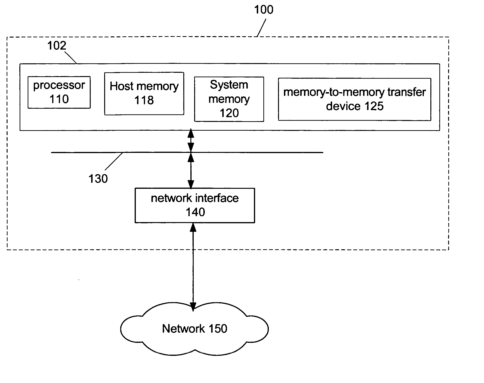
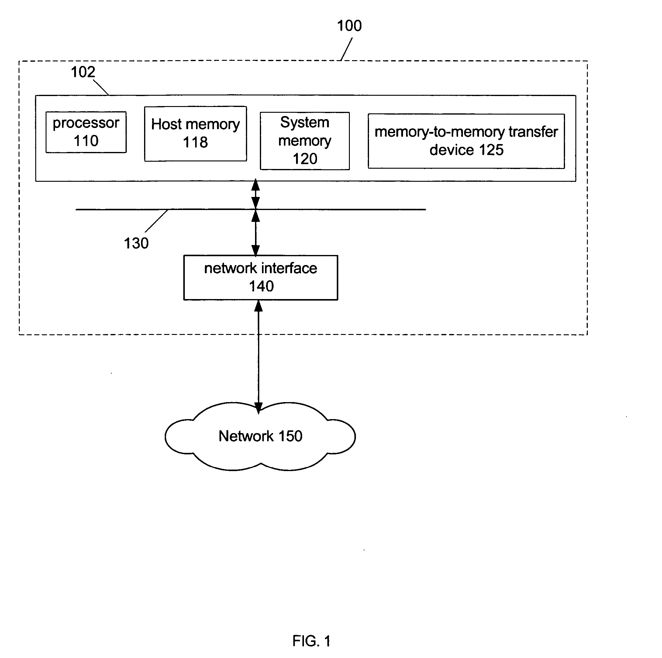
[0010]FIG. 1 depicts an example computer system 100 that can use embodiments of the present invention. Computer system 100 may include host system 102, bus 130, and network interface 140. Host system 102, bus 130, and network interface 140 may intercommunicate using a single circuit board, such as, for example, a system motherboard. The system motherboard may include a graphics interface in compliance for example with the VGA and SVGA standar...


PUM


Abstract

Techniques for accelerating network receive side processing of packets. Packets may be associated into flow groupings and stored in flow buffers. Packet headers that are available for TCP/IP processing may be provided for processing. If a payload associated with a header is not available for processing then a descriptor associated with the header is tagged as indicating the payload is not available for processing.

Description

RELATED ART [0001] Networking is an integral part of computer systems. Advances in network bandwidths, however, have not been fully utilized due to latency that may be associated with processing protocol stacks. Latency may result from bottlenecks in the computer system from using the core processing module of a host processor to perform slow memory access functions such as data movement, as well as host processor stalls related to data accesses missing the host processor caches. A protocol stack refers to a set of procedures and programs that may be executed to handle packets sent over a network, where the packets may conform to a specified protocol. For example, TCP / IP (Transport Control Protocol / Internet Protocol) packets may be processed using a TCP / IP stack.BRIEF DESCRIPTION OF THE DRAWINGS [0002]FIG. 1 depicts an example computer system that can use embodiments of the present invention. [0003]FIG. 2 depicts an example of machine-executable instructions, in accordance with an e...

Claims


Application Information

Patent Timeline
IPC IPC(8): H04L12/56H04L12/28
CPCH04L12/5693H04L47/621H04L49/90H04L69/161H04L49/9068H04L69/16H04L69/22H04L49/9042H04L47/50
Inventor RONCIAK, JOHNLEECH, CHRISTOPHERDEUSKAR, PRAFULLABRANDEBURG, JESSECONNOR, PATRICK
Owner INTEL CORP
Why Eureka
Try Eureka