Method for intensity modulated radiation treatment using independent collimator jaws

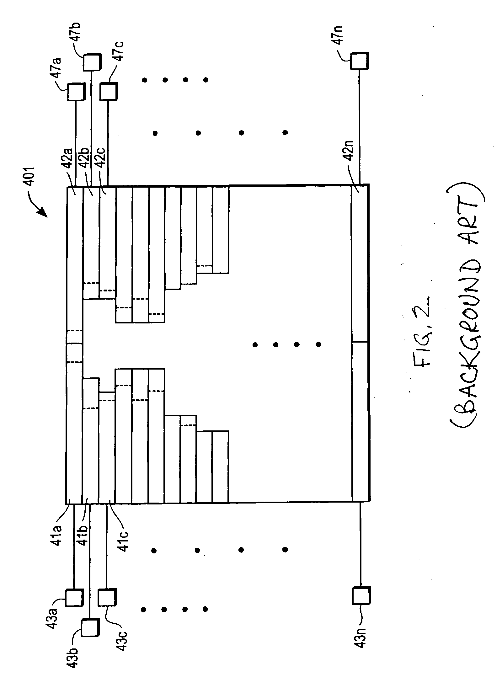
a collimator jaw and intensity modulation technology, applied in radiation therapy, diaphragm/collimeter handling, therapy, etc., can solve the problems of affecting the treatment effect of patients, the mlc 401 becomes more complicated, and the radiation field alone provides limited freedom in shaping the volume of high radiation dose to conform to tumors, and adverse effects can arise in the patient being treated

Inactive Publication Date: 2006-03-02
PROWESS
View PDF4 Cites 51 Cited by
  • Summary
  • Abstract
  • Description
  • Claims
  • Application Information

AI Technical Summary

Benefits of technology

[0024] The combination of directly optimizing the shapes and weights of the field segments and the freedom of allowing the apertures to take different orientations provides added freedom in the treatment planning problem. The present invention uses this added freedom to compensate for the limitations posed by background art radiation therapy systems with collimator jaws only that form rectangular radiation field segments. In particular, the method of the present invention makes it possible to generate IMRT treatment plans with radiation field segments that a highly conformal to the target tumor without using impractically large numbers of radiation field segments, as required by the background art.

Problems solved by technology

The more leaves that are used, the more complicated the MLC 401 becomes.
While background art treatment planning using the “forward-planning” technique for conventional cancer radiation treatment has achieved some success, shaping the radiation field alone provides limited freedom in shaping the volume of the high radiation dose to conform to the tumor.
As a result, adverse effects can arise in the patient being treated because of irradiation of normal structures in the “forward-planning” technique to treatment planning.
The cost of a MLC is a substantial portion of the cost of the radiation delivery device (i.e., the LINAC).
However, as discussed above, not all LINACs are equipped with a MLC due to the substantial cost involved.
In fact, older LINACs currently in use are not equipped with a MLC but only with collimator jaws.
A limitation of these independent collimator jaws is that these radiation blocking devices can only form rectangular fields.
Due to this limitation, the delivery of IMRT using collimator jaws alone was thought to be impractical.
However, use of such a relocatable mask introduces different practical issues and adds cost.
Thus, to date there is no known treatment planning system for planning IMRT treatments using collimator jaws alone that does not include practical implementation problems and increased costs.
However, these background art techniques for IMRT treatment planning typically perform the optimizing step without consideration of the delivery constraints of either the MLC or the LINAC.
Ignoring these delivery constraints of the LINAC and MLC in the optimizing step of the treatment plan makes the second step of converting from the intensity maps to deliverable field segments more complex.
As a result of this increased complexity, a large number of field segments are required to produce the desired radiation intensity distribution.
Therefore, as a result of the size of the beamlets, the shape of the square radiation field segment fails to conform to the shape of the target tumor.
Since the target tumor can be viewed from different beam angles in the beam's eye view (BEV), a fixed collimator would not allow the MLC to best conform to the shape of the tumor.
This limitation of the MLC further increases the complexity of delivery constraints that should be considered in treatment planning systems.
As discussed above, each of the background art techniques has certain practical limitations.
Further, the use of collimator jaws alone further constrains the shape of the radiation field segments to rectangles.
Such a large number of rectangular fields would require hours of time to deliver and would clearly be impractical.

Method used


Image

  • Method for intensity modulated radiation treatment using independent collimator jaws
  • Method for intensity modulated radiation treatment using independent collimator jaws
  • Method for intensity modulated radiation treatment using independent collimator jaws

Examples


Embodiment Construction

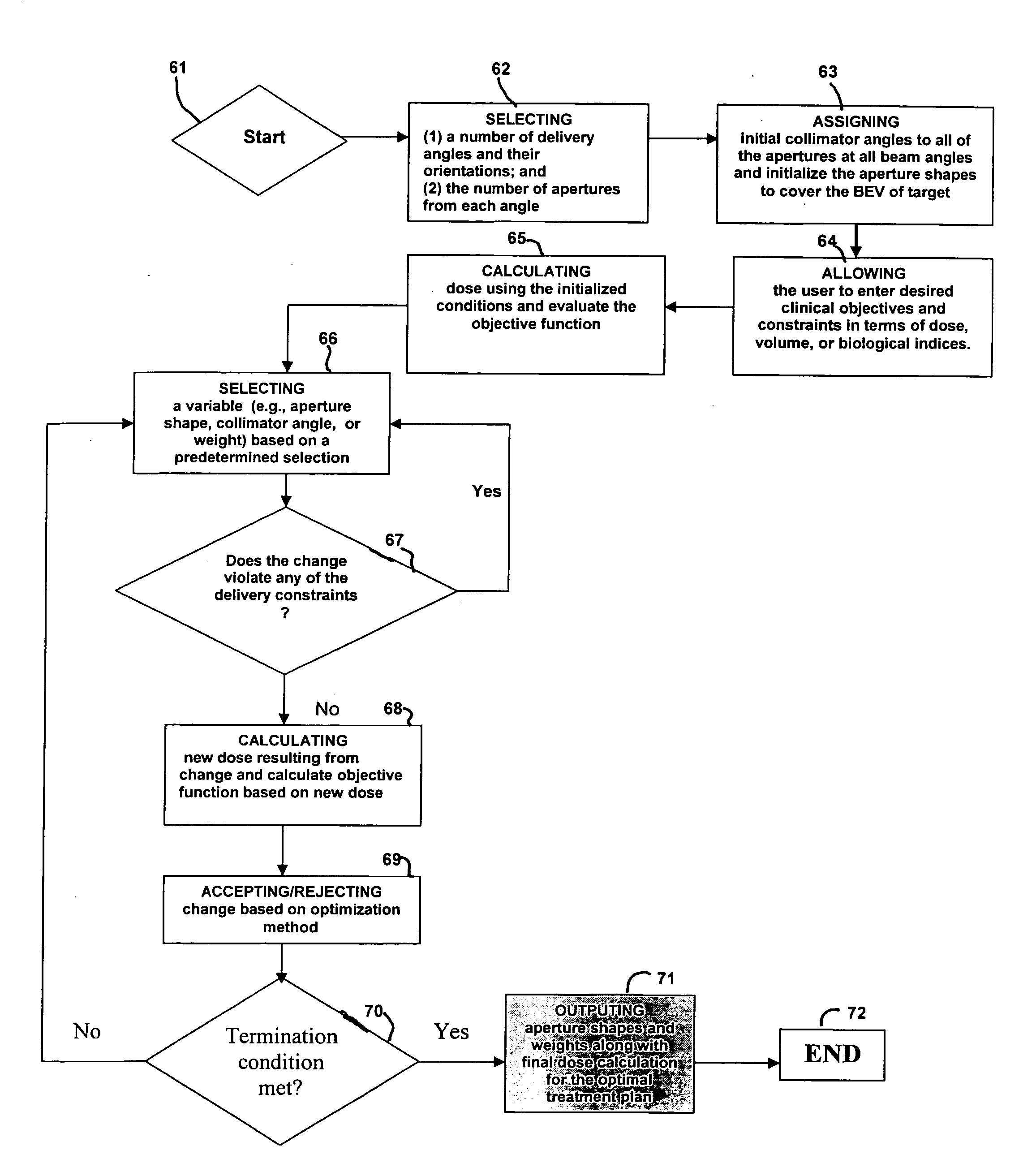
[0032] The present invention enables IMRT treatments to be delivered with the use of simple independent collimator jaws. Instead of optimizing the intensities of beamlets, the present invention directly optimizes the field shapes and the corresponding weights of the rectangular apertures formed by the simple independent collimator jaws. Furthermore, the optimization step of the present invention does not explicitly use beamlets and thus allows the simple independent collimator jaws to form field boundaries at any position (i.e., not merely at increments of a finite-sized beamlet). The method of the present invention allows each rectangular field shaped by the collimator jaws to take a different collimator angle. The combination of these optimally weighted apertures with optimal collimator angles at every beam angle creates a highly modulated radiation intensity distribution for achieving the clinical objectives of the treatment plan. Since the field boundaries are not limited by the...


PUM


Abstract

The present invention is a method for treatment planning and delivery of the radiation treatment plan for the intensity-modulated radiation therapy (IMRT) treatment using linear accelerators (LINACs) not equipped with a multileaf collimator (MLC). The present invention makes the use of a simpler collimator consisting of only 4 collimator jaws. In addition, the method for treatment planning of the present invention may be performed on a computer separate from the LINAC control computer, so that the treatment planning system can generate IMRT treatment plans for LINACs and collimator jaws from different vendors.

Description

BACKGROUND OF THE INVENTION [0001] The present invention relates to a computerized method for the planning and delivery of radiation therapy. In particular, it is a computerized method that determines the optimal radiation treatment plan for a patient using specified clinical objectives. [0002] In general, radiation therapy is the use of ionizing radiation for the treatment of disease. The most common use is in the treatment of cancer. The goal of radiation therapy in cancer treatment is to destroy any malignant cells while minimizing the damage to healthy tissue. One example of a device for delivering the radiation to a patient is a linear accelerator (LINAC). A LINAC is a machine that generates a high-energy beam of radiation that can be controlled and directed onto specified locations. LINACs are sometimes equipped with a multi-leaf collimator (MLC). A MLC is a device that shapes each individual beam of radiation. Alternatively, a LINAC may not be equipped with a MLC, but instead...

Claims


Application Information

Patent Timeline
Patent Type & Authority Applications(United States)
IPC IPC(8): A61N5/10
CPCA61N5/1042A61N5/103
Inventor NGUYEN, JOHN
Owner PROWESS
Why Eureka
Try Eureka