Device for fusing toner on print medium

a technology of toner and print medium, which is applied in the direction of electrographic process equipment, instruments, optics, etc., can solve the problems of large temperature difference between, image printing equipment may malfunction, and the life span of the image printing equipment is reduced

Inactive Publication Date: 2006-03-02
S PRINTING SOLUTION CO LTD
View PDF5 Cites 6 Cited by
  • Summary
  • Abstract
  • Description
  • Claims
  • Application Information

AI Technical Summary

Benefits of technology

[0010] The present invention substantially solves the above and other problems and provides other advantages, and provides a fusing unit for locally heating a toner fusing unit corresponding to the size of paper within a short warm-up time by using a predetermined eddy current.
[0011] The present invention also provides a fusing unit for locally heating a toner fusing unit corresponding to a paper size within a short warm-up time by simultaneously using induction heating and resistance heating.
[0012] The present invention also provides a fusing device for locally heating a toner fusing unit corresponding to a paper size within a short warm-up time by using an eddy current generated by a transformer.
[0013] The present invention also provides a fusing device for locally heating a toner fusing unit corresponding to a paper size within a short warm-up time by simultaneously using induction heating and resistance heating.

Problems solved by technology

However, a conventional image printing apparatus heats the entire surface of a fusing roller regardless of the size of paper to be printed.
Thus, when a toner image is printed on paper having a smaller size than that of the fusing roller, there is a large temperature difference created between a region in which the paper passes through the fusing roller, and a region in which the paper does not pass through the fusing roller.
When the image printing apparatus is used over a long period of time, the image printing apparatus may malfunction due to the rapid temperature increase in the region in which the paper does not pass through the fusing roller.
In addition, due to uneven heating of the fusing roller, the life span of the image printing apparatus is reduced.
Thus, a user is required to wait for a long warm-up time when printing an image, regardless of the paper size.

Method used


Image

  • Device for fusing toner on print medium
  • Device for fusing toner on print medium
  • Device for fusing toner on print medium

Examples


Embodiment Construction

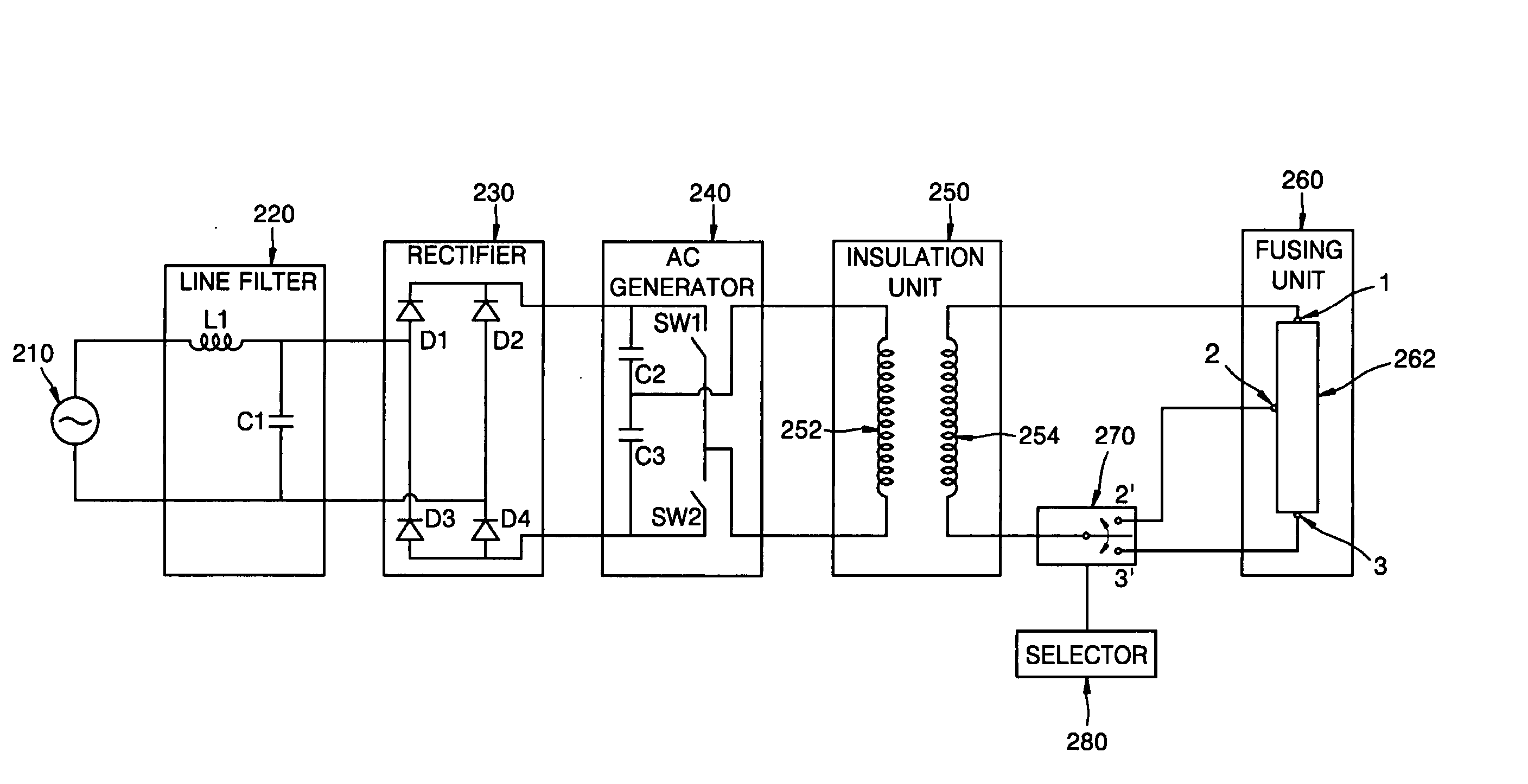
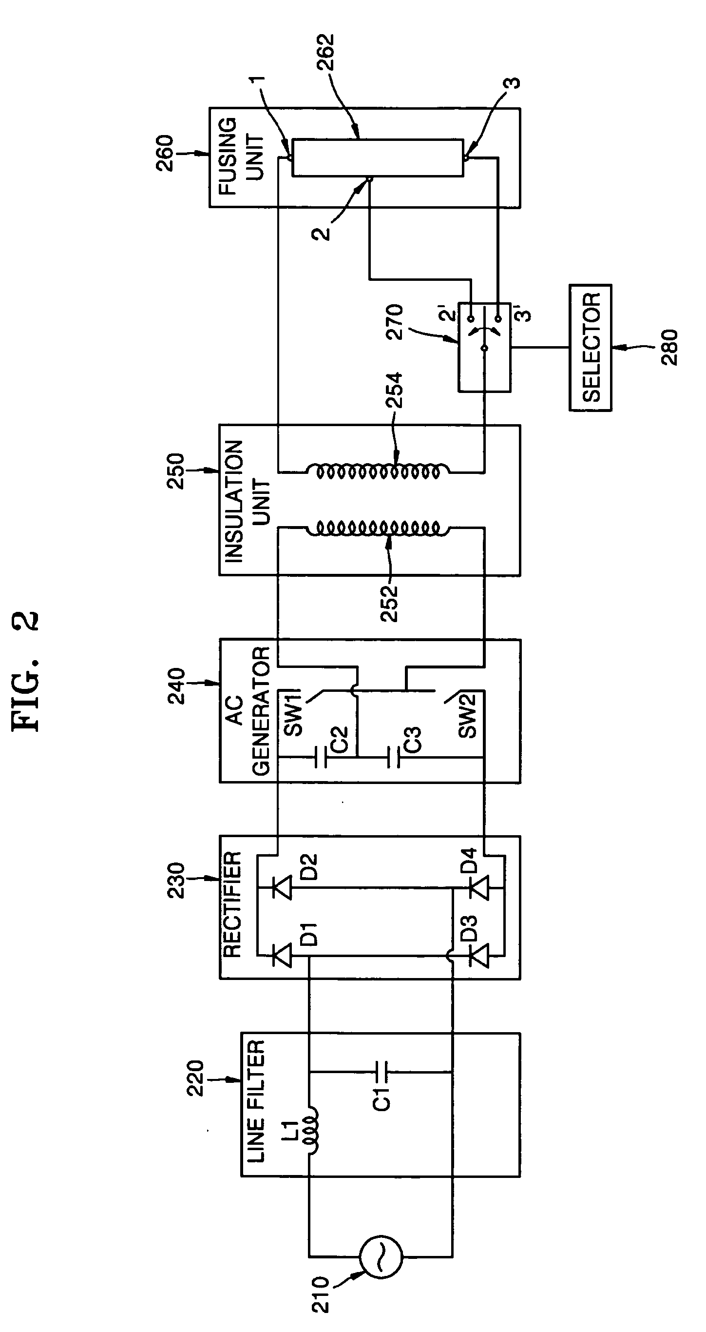
[0029]FIG. 2 is a functional block diagram of a fusing device according to an embodiment of the present invention. Referring to FIG. 2, the fusing device comprises a power supply unit 210, a line filter 220, a rectifier 230, an AC generator 240, an insulation unit 250, a fusing unit 260 having a heater 262, a controller 270, and a selector 280. The power supply unit 210 supplies an AC signal having a predetermined amplitude and frequency. The line filter 220 includes an inductor L1 and a capacitor C1. The line filter 220 removes harmonics components included in the AC signal received from the power supply unit 210. The line filter 220 is illustrated as one type of a line filter for illustrating an exemplary embodiment of the present invention, and is not limited thereto. In yet other embodiments of the present invention, another type of line filter may be used as the line filter 220 without departing from the scope of the present invention.

[0030] The rectifier 230 generates a DC si...


PUM


Abstract

A fusing device for fusing a predetermined toner image on paper, and which controls the heating range of a fusing unit by inputting an eddy current generated by a transformer to a terminal corresponding to the size of paper selected from a plurality of terminals of the fusing unit. The fusing device includes a power supply unit to which a predetermined alternating current is input and which generates an induced current in response to the input alternating current, a fusing unit being resistance-heated and induction-heated by the induced current and fusing the toner image on the paper using the generated heat, and a controller for controlling the induced current supplied to the fusing unit according to the size of the paper.

Description

CROSS-REFERENCE TO RELATED PATENT APPLICATIONS [0001] This application claims the benefit under 35 U.S.C. §119(a) of Korean Patent Application No. 10-2004-0069561, filed in the Korean Intellectual Property Office on Sep. 1, 2004, the entire disclosure of which is incorporated herein by reference. BACKGROUND OF THE INVENTION [0002] 1. Field of the Invention [0003] The present invention relates to a device for fusing a predetermined toner image on paper. More particularly, the present invention relates to a fusing device which controls the heating range of a fusing unit by inputting an eddy current generated by a transformer to a terminal corresponding to the size of paper selected from a plurality of terminals of the fusing unit. [0004] 2. Description of the Related Art [0005] A conventional image printing apparatus comprises a fusing device which applies a predetermined pressure and amount of heat to a toner so as to fuse a predetermined toner image on paper. The fusing device inclu...

Claims


Application Information

Patent Timeline
Patent Type & Authority Applications(United States)
IPC IPC(8): G03G15/20
CPCG03G2215/2006G03G15/80G03G15/2042G03G15/2039G03G15/5004G03G15/2053G03G2215/2016
Inventor CHAE, YOUNG-MINKWON, JOONG-GIKIM, HWAN-GUEMCHO, DURK-HYUNHAN, SANG-YONG
Owner S PRINTING SOLUTION CO LTD
Why Eureka
Try Eureka