
Direct-current large-current fused salt defreezing and preheating device of groove type vacuum heat collecting pipe

A technology of vacuum heat collecting tube and preheating device, which is applied to a preheating device, in the field of melting salt thawing in the vacuum heat collecting tube, to achieve the effects of small heat transfer resistance, short preheating time and saving internal space

Active Publication Date: 2014-04-09
河北井矿新能源科技有限公司
View PDF4 Cites 5 Cited by
  • Summary
  • Abstract
  • Description
  • Claims
  • Application Information

AI Technical Summary

Problems solved by technology

It solves the problem of thawing molten salt in the vacuum heat collecting tube of the trough system, and provides a technical means to prevent the freezing of molten salt in the vacuum heat collecting tube. At the same time, because the system needs to preheat the heat collector and its pipeline before filling the salt , in order to reduce the thermal stress damage of the pipeline, the present invention is also a technical device for salt-filled preheating of the vacuum heat collection pipeline

Method used


Image

  • Direct-current large-current fused salt defreezing and preheating device of groove type vacuum heat collecting pipe
  • Direct-current large-current fused salt defreezing and preheating device of groove type vacuum heat collecting pipe
  • Direct-current large-current fused salt defreezing and preheating device of groove type vacuum heat collecting pipe

Examples


Embodiment Construction

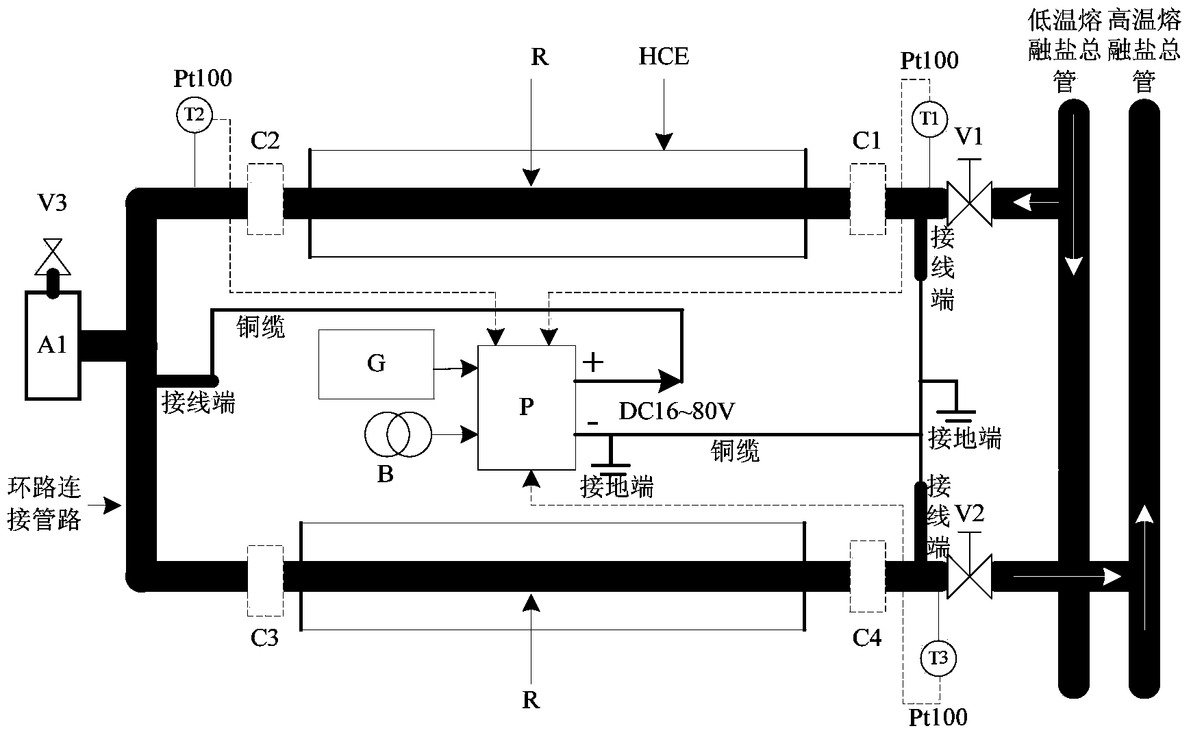
[0024] combine figure 1 , further explain the specific implementation of this patent:

[0025] The on-site transformer B provides the power required for thawing and preheating the collectors of the entire power plant, and the backup generator G only provides the power required for thawing and preheating the collectors of a single circuit when the system is powered off or requires special treatment.

[0026] The AC / DC conversion module and control system P are responsible for providing low-voltage and high-current DC power and can adjust the output voltage value for different SCA lengths to provide corresponding electric power. The maximum DC output voltage is 80V.

[0027] According to the output current capability of the AC / DC conversion module, the number of loops it can handle is determined, and each AC / DC conversion module can handle 1 to 2 loops.

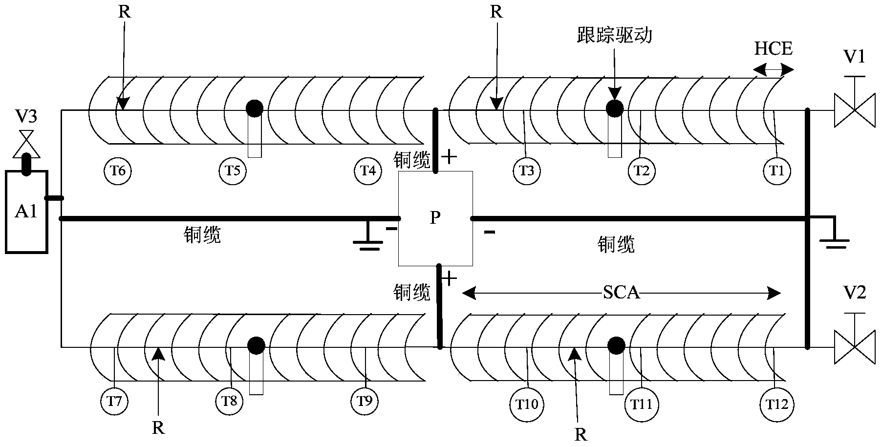
[0028] T1, T2, and T3 are used as temperature sensors at the head, tail and middle of the circuit for system thawing and pre...


PUM


Abstract

The invention discloses a direct-current large-current fused salt defreezing and preheating device of a groove type vacuum heat collecting pipe and belongs to the technical field of thermal equipment. The direct-current large-current fused salt defreezing and preheating device is composed of a pipeline system and a direct electric heating system. The pipeline system comprises a voltage limiting valve V1, a voltage limiting valve V2, a ceramic electric insulating structure used for being connected with a heat absorber supporting mechanism, an expansion tank and a voltage limiting valve V3. The direct electric heating system comprises a field transformer, a standby alternator, an AC / DC module used for AC-DC conversion, a connection copper cable, a terminal block, a Pt100 temperature sensor T1, a Pt100 temperature sensor T2 and a Pt100 temperature sensor T3, wherein the Pt100 temperature sensor T1, the Pt100 temperature sensor T2 and the Pt100 temperature sensor T3 are used for controlling. According to the direct-current large-current fused salt defrosting and preheating device of the groove type vacuum heat collecting pipe, a body resistor in a stainless steel inner pipe of the vacuum heat collecting pipe is used as an electric-heating heating element, the problems of freezing and blocking of fused salt and preheating starting in the groove type system vacuum heat collecting pipe are solved, and the direct-current large-current fused salt defrosting and preheating device has the advantages of being convenient to carry out, capable of saving space in the vacuum heat collecting pipe, even in peripheral heating, little in heat transfer resistance and short in defreezing and preheating time.

Description

technical field [0001] The patent of the present invention is aimed at a trough-type concentrating solar thermal power generation system, and is a device for thawing and preheating molten salt in a vacuum heat collecting tube. It is a start-up preheating and freezing blocking removal device based on molten salt as the heat transfer working medium of the trough solar concentrating thermal power generation system. When the molten salt freezes in the vacuum heat collecting tube, it can be thawed quickly and conveniently without occupying the inner space of the heat collecting tube. It can provide freezing blockage removal and start-up preheating for the trough solar thermal power generation system where molten salt is used as the heat collection and heat transfer medium, and improve the operating efficiency and safety performance of the system. Background technique [0002] At present, countries all over the world have strengthened the research and development of clean energy ...

Claims


Application Information

Patent Timeline
Patent Type & Authority Applications(China)
IPC IPC(8): F24J2/46F16L53/00
CPCY02E10/40
Inventor 杜春旭吴玉庭马重芳张业强
Owner 河北井矿新能源科技有限公司
Learn More