Flexible bipolar plate

a bipolar plate, flexible technology, applied in the field of bipolar plates, can solve the problems of temperature change, dimensional change affecting the compressive force imparted on the fuel cell, and the level of humidification of the active element in the fuel cell

Active Publication Date: 2006-03-02
GM GLOBAL TECH OPERATIONS LLC
View PDF5 Cites 41 Cited by
  • Summary
  • Abstract
  • Description
  • Claims
  • Application Information

AI Technical Summary

Benefits of technology

[0012] A method of maintaining a compression of a fuel cell stack in a predetermined range during dimensional changes in fuel cells of the fuel cell stack is disclosed. The method includes: (1) operating the fuel cell stack to

Problems solved by technology

One of the causes of the dimensional changes is the temperature change that occurs during operation of the fuel cells.
As a result, as temperature changes occur, the various components of the fuel cell may expand or contract at differing rates, thereby causing dimensional changes that affect the compressive force imparted on the fuel cells.
Another cause of dimensional changes is the level of humidification of the active element in the fuel cells.
The swelling and shrinking of the active element can cause dimensional changes to occur which alter the compressive force imparted on the fuel cells.
Furthermore, if the fuel cell stack is subjected to a freezing environment, the freezing and thawing of water within the fuel cell stack can cause dimensional changes to occur.
Mo

Method used


Image

  • Flexible bipolar plate
  • Flexible bipolar plate
  • Flexible bipolar plate

Examples


example 1

EXAMPLE 1

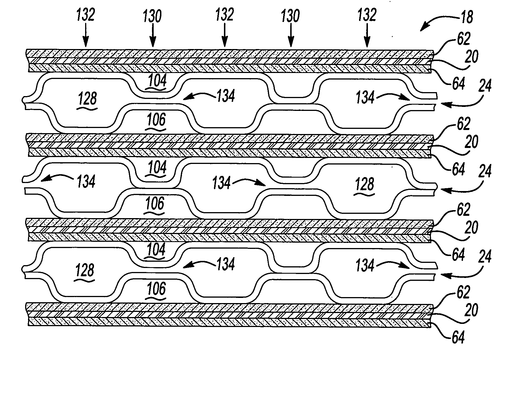
[0033] Referring now to FIG. 5, a comparison of the stiffness of a typical prior art bipolar plate to a bipolar plate of the present invention is shown along with a stiffness of a typical diffusion media member. In the prior art bipolar plate, all opposing pairs of lands within the coolant flow field were in contact with one another and brazed together. In the bipolar plate of the present invention, every other opposing pair of lands 130 were in contact with one another and brazed together while the remaining opposing pairs of lands had a gap 134 therebetween. The typical diffusion media member was a Toray 060 paper. The bipolar plates and the Toray paper were individually compressed between two rigid surfaces and the resulting stiffness curves were generated using the finite element method. Based on this method, curves 140, 142 and 144 for the respective prior art bipolar plate, bipolar plate of the current invention, and Toray 060 paper were developed. The slopes of these...

example 2

EXAMPLE 2

[0034] To evaluate how much reduction of over compression the bipolar plate of the present invention can achieve, the contact pressure in a single cell consisting of two bipolar plates, two 0.18 mm-thick diffusion media members, and an MEA with a 0.018 mm-thick membrane was investigated. The diffusion media members were Toray 060 paper. The membrane was Gore 55 series with a swelling ratio of 0.38 in the thickness direction. The study was performed using the finite element method. After the cell was compressed to 450 PSI, the membrane was allowed to fully hydrate and swell while the two rigid surfaces on either side of the cell were fixed in place. It was found that an additional contact pressure of 45 PSI occurred in the land area after the membrane was fully hydrated. When the same analysis was performed using a conventional prior art bipolar plate, additional contact pressure of 110 PSI was found. The results of this test suggest that the use of a bipolar plate of the pr...


PUM


Abstract

The present invention provides for a construction for a bipolar plate for a fuel cell stack that enables the bipolar plate to be a more compliant member in the fuel cell stack. The bipolar plate can be configured to provide varying levels of compliance, as demanded by the design of the fuel cell stack. The bipolar plate can be more compliant than the diffusion media members and the active elements used to form the individual fuel cells. The compliant nature of the individual bipolar plates enables localized dimensional changes that occur within the fuel cell stack to be compensated by a localized deformation of the portions of the bipolar plate within that region. The bipolar plate has an internal coolant flow field where some opposing pairs of lands are spaced apart with a gap therebetween while other opposing pairs of lands are in contact with one another.

Description

FIELD OF THE INVENTION [0001] The present invention relates to fuel cell stacks and, more particularly to bipolar plates used in fuel cell stacks. BACKGROUND OF THE INVENTION [0002] Fuel cells have been proposed as a power source for electric vehicles, stationary power supplies and other applications. One known fuel cell is the PEM (i.e., Proton Exchange Membrane) fuel cell, which is an acid-type fuel cell. Other types of fuel cells include alkaline-type, molten-carbonate-type and solid-oxide-type. A PEM fuel cell includes a so-called MEA (“membrane-electrode-assembly”) comprising a thin, solid polymer membrane-electrolyte (active element) having an anode on one face and a cathode on the opposite face. The MEA is sandwiched between a pair of electrically conductive contact elements which serve as current collectors for the anode and cathode, which may contain appropriate channels and openings therein for distributing the fuel cell's gaseous reactants (i.e., H2 and O2 / air) over the s...

Claims


Application Information

Patent Timeline
IPC IPC(8): H01M8/02H01M4/94
CPCH01M8/0228H01M8/0254H01M8/0265Y02E60/50H01M8/241H01M2008/1095H01M8/0267H01M8/2483H01M8/0258H01M8/0271
Inventor LAI, YEH-HUNG
Owner GM GLOBAL TECH OPERATIONS LLC
Why Eureka
Try Eureka