Automobile racing suspension system

a suspension system and racing technology, applied in vehicle springs, sports apparatus, video games, etc., can solve the problems of bouncing and swaying, the most undesirable at speeds over 50, and the least effective, so as to improve the driving experience, and improve the effect of mechanical downfor

Inactive Publication Date: 2006-03-02
GILMARTIN MICHAEL D
View PDF2 Cites 19 Cited by
  • Summary
  • Abstract
  • Description
  • Claims
  • Application Information

AI Technical Summary

Benefits of technology

[0009] The present invention comprises a suspension system with two parallel, helical pull-springs closely coupled to the highest, outermost point of the vertical linkage, having either a left or a right hand coil helix working in unison or sequentially. An object and advantage of the present invention is to provide a mechanism to control or provide greater security of un-sprung wheel assembly and lateral weight transfer.
[0010] An object and advantage of the present invention is to keep the tires of high speed vehicles on the road surface for the greatest possible percentage of circuit distance. In airborne wheels which are un-controlled, surface protrusions and bumps in the road are most often the cause of upward vertical travel. Additionally, the forward speed of the vehicle has the natural tendency to lift the wheel assembly. Indentations (“potholes”), depressions at high speeds are encountered on the forward side and are therefore upward thrust. The result is undesirable vertical lift of the assembly and the present invention provides an appropriate intervention required for better and improved control and road handling.
[0011] Another object and advantage of the present invention is to prevent high speed vehicles, which have low center of gravity, from side drift and surface skid. The prevent invention provides a counter-balanced stress that is directed at approximately a 45 degree angle to the outer section of the lower A-frame of a vehicle. The stress can be expressed as a vector having comparable magnitude and opposing direction as the forces on the vehicle caused by the road and racing the vehicle at high speeds, around curves, etc.
[0012] In a preferred embodiment, the present invention is an automotive racing vehicle suspension system coupled between a vehicle body and a rotatable wheel, the suspension system comprising: an upper wheel assembly control arm coupled at a proximal end to the vehicle body; a lower A-frame portion rigidly suspended at a proximal end below the upper wheel assembly control arm; a vertical link coupled between a distal end of the upper wheel assembly control arm and a distal end of the lower A-frame portion, the vertical link rotatably coupled to a hub assembly; a leaf spring attached to the upper wheel assembly control arm for providing resilient resistance to vertical motion above or below the upper wheel assembly control arm; at least one shock absorber coupled between the chassis and the lower A-frame portion for providing resilient resistance to motion between the upper wheel assembly control arm and the lower A-frame portion which causes a compressive force in the at least one shock absorber; and at least one pull-spring coupled between the upper wheel assembly control arm and the lower A-frame portion for providing resilient resistance to motion between the upper wheel assembly control arm and the lower A-frame portion which causes a tensile force in the at least one pull-spring.
[0013] In another preferred embodiment of the present invention, the at least one pull-spring is a helical coil spring.
[0014] In another preferred embodiment of the present invention, the at least one pull-spring is an elastic member.

Problems solved by technology

This up-and-down movement, however, causes bouncing and swaying after each bump and is very uncomfortable.
However, in the case of racing vehicles that run at high speed which typically utilize pushrod suspension systems, the conditions are very different.
Of all the methods currently in use to control an un-sprung wheel assembly given vehicle weight, road surface irregularity and lateral forces, the push-rod-to-compression-spring via fulcrum or rocker is the least effective and the most undesirable at speeds in excess of 50 mph.
By the time the weakened impact encounters the static coil springs, another surface irregularity is encountered.
This causes undesirable stresses to both vehicle and driver.
The stresses imposed on the vehicle and passengers are difficult to evaluate, they are inevitably harmful to overall structural integrity of the vehicle.
In addition, those stresses are exerted at an approximately 45-degree angle to the outer section of the lower A-frame, which contributes to side drift and surface skid of the wheels.
This type of situation can be particularly critical in performance of racing vehicles, primarily due to the fact that racing vehicles such as those shown in FIGS. 1 and 2 (PRIOR ART) have a very low center of gravity, thus making them inherently susceptible to side drift and surface skid.

Method used


Image

  • Automobile racing suspension system
  • Automobile racing suspension system
  • Automobile racing suspension system

Examples


Embodiment Construction

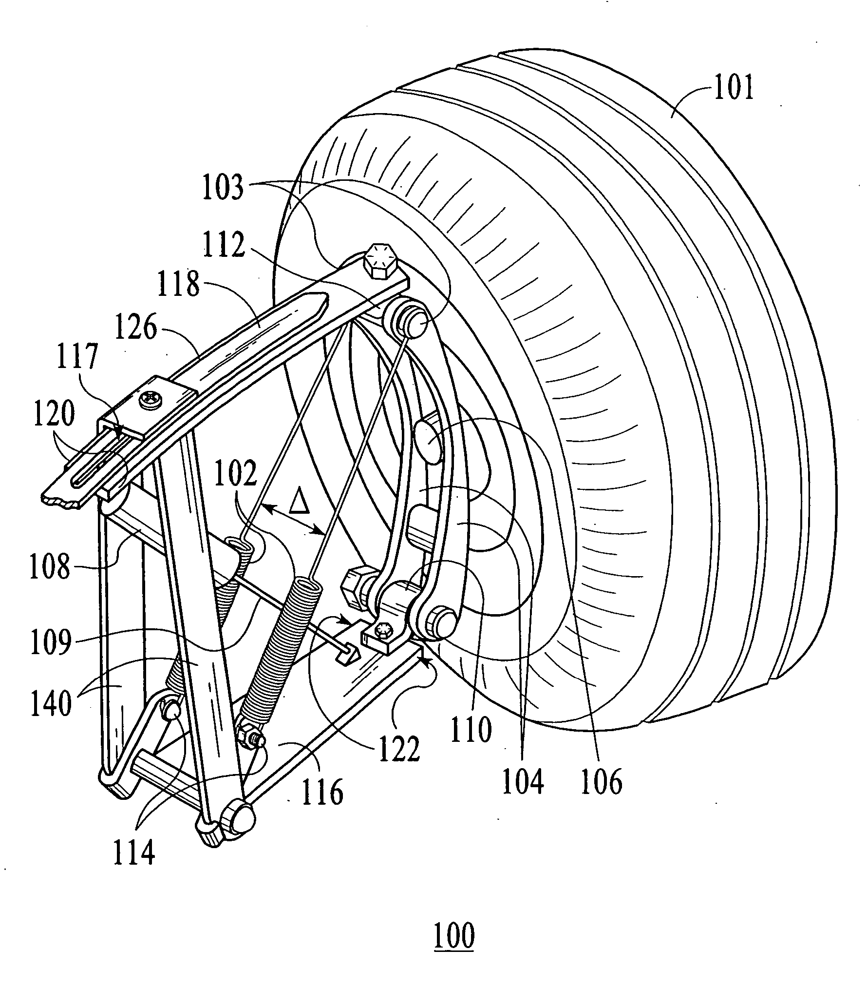
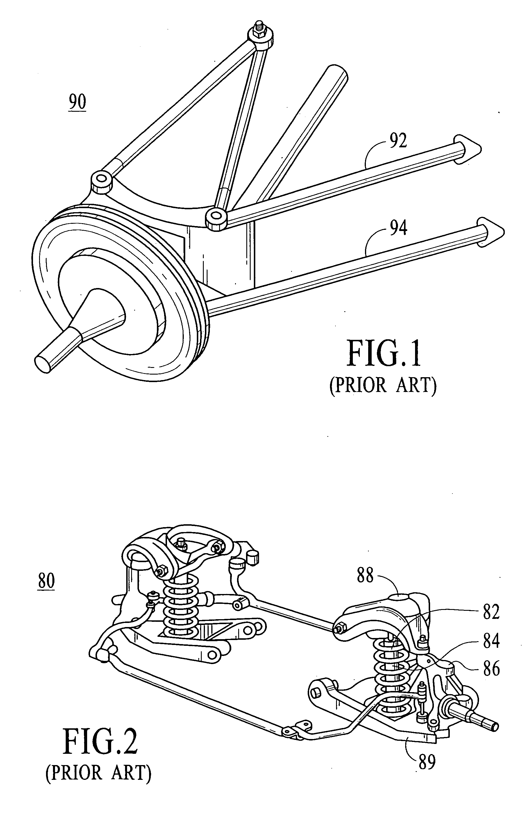
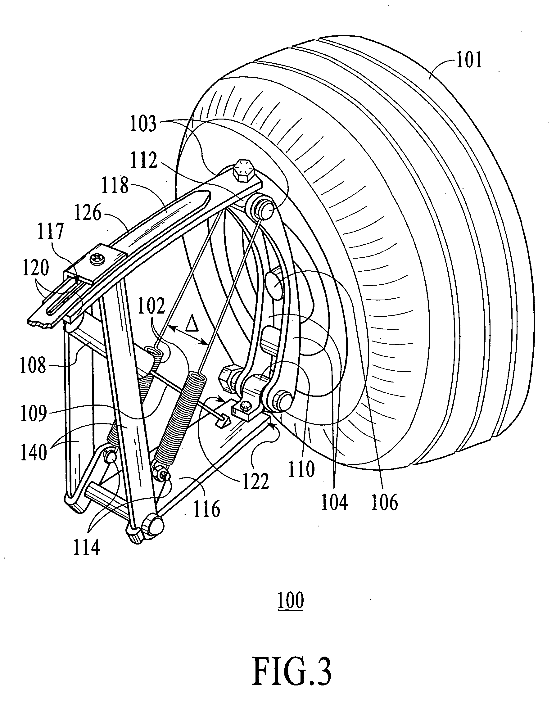
[0035] The description that follows is presented to enable one skilled in the art to make and use the present invention, and is provided in the context of a particular application and its requirements. Various modifications to the disclosed embodiments will be apparent to those skilled in the art, and the general principals discussed below may be applied to other embodiments and applications without departing from the scope and spirit of the invention. Therefore, the invention is not intended to be limited to the embodiments disclosed, but the invention is to be given the largest possible scope which is consistent with the principals and features described herein.

[0036] It will be understood that in the event parts of different embodiments have similar functions or uses, they may have been given similar or identical reference numerals and descriptions. It will be understood that such duplication of reference numerals is intended solely for efficiency and ease of understanding the p...


PUM


Abstract

An automotive racing vehicle suspension system coupled between a vehicle body and a rotatable wheel, the suspension system comprising: an upper wheel assembly control arm coupled at a proximal end to the vehicle body; a lower A-frame portion rigidly suspended at a proximal end below the upper wheel assembly control arm; a vertical link coupled between a distal end of the upper wheel assembly control arm and a distal end of the lower A-frame portion, the vertical link rotatably coupled to a hub assembly; a leaf spring attached to the upper wheel assembly control arm for providing resilient resistance to vertical motion above or below the upper wheel assembly control arm; at least one shock absorber coupled between the chassis and the lower A-frame portion for providing resilient resistance to motion between the upper wheel assembly control arm and the lower A-frame portion which causes a compressive force in the at least one shock absorber; and at least one pull-spring coupled between the upper wheel assembly control arm and the lower A-frame portion for providing resilient resistance to motion between the upper wheel assembly control arm and the lower A-frame portion which causes a tensile force in the at least one pull-spring.

Description

FIELD OF THE INVENTION [0001] The present invention relates generally to automotive suspension systems, and more particularly, to suspension systems for sports and racing cars. BACKGROUND OF THE INVENTION [0002] Automotive suspension systems 90 of the prior art utilize front and rear springs to suspend the weight of the vehicle. The suspension springs 92 used on typical cars and trucks are constructed in a variety of types, shapes, sizes, rates, and capacities, including leaf springs, coil springs, air springs, and torsion bars. These suspension springs 92 are used in sets of four for each vehicle, or they may be paired off in various combinations and attached by any of several different mounting systems and techniques. As best shown in FIG. 1, common suspension systems 90 of the prior art also contains shock absorbers and / or struts 94, and sway bars. Improvements in suspension and steering, increased strength and durability of components, and advances in tire design and constructio...

Claims


Application Information

Patent Timeline
Patent Type & Authority Applications(United States)
IPC IPC(8): A63F9/24
CPCB60G3/28B60G11/36B60G17/023B60G2200/144B60G2202/114B60G2202/12B60G2500/20B60G2202/24B60G2204/124B60G2204/129B60G2204/4232B60G2300/27B60G2202/122
Inventor GILMARTIN, MICHAEL D.
Owner GILMARTIN MICHAEL D
Why Eureka
Try Eureka