Hydrogel for use in downhole seal applications

a technology of hydrogel and seal body, which is applied in the direction of sealing/packing, other chemical processes, borehole/well accessories, etc., can solve the problems of water starting to absorb and swell, and achieve the effect of preventing seal failure and high swelling for

Inactive Publication Date: 2006-03-02
SCHLUMBERGER TECH CORP
View PDF16 Cites 17 Cited by
  • Summary
  • Abstract
  • Description
  • Claims
  • Application Information

AI Technical Summary

Benefits of technology

[0011] Once incorporated into the seal body, the hydrogel provides several advantages over typical seal body components. First, the hydrogel allows the seal to be energized via swelling. Since hydrogel can swell as much as 1,000 times in volume, high swelling force can be utilized to energize the main seal body as well as anti-extrusion device.
[0012] The hydrogel may also allow potential leak paths to be sealed. Hydrogel swells in aqueous environment. That is, whenever it contacts an aqueous medium, it starts to absorb water and swell. For applications with hard-to-seal voids or surfaces, hydrogel can stop leak via swelling. Swelling leads to greater squeeze of main seal body. This, in turn, seals the leak path and prevents seal failure.

Problems solved by technology

That is, whenever it contacts an aqueous medium, it starts to absorb water and swell.

Method used


Image

  • Hydrogel for use in downhole seal applications
  • Hydrogel for use in downhole seal applications
  • Hydrogel for use in downhole seal applications

Examples


example 1

Packer Elements

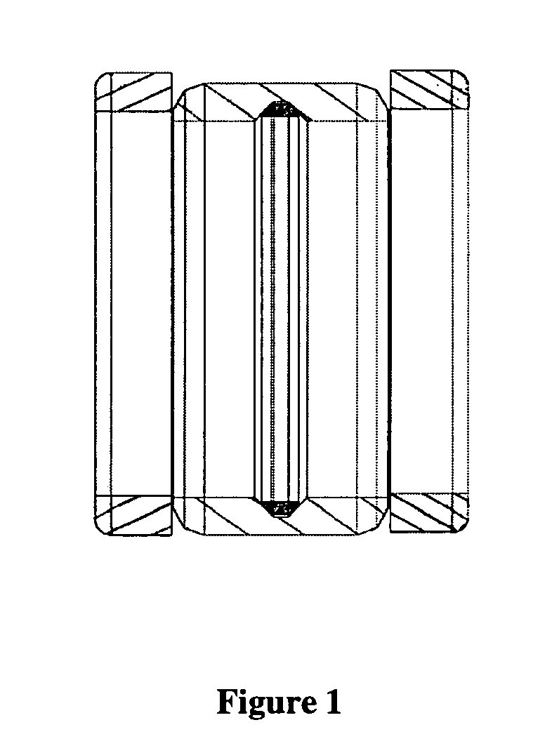
[0030]FIG. 1 shows three-piece rubber element array or packer element 10, such as that commonly used in downhole packers. The packer elements are external packer seal bodies that seal the annulus space between tubing and casing (not shown). Elements are energized by axial deflection of the seal bodies after the packer is run into the hole. Commonly used packer elements typically consist of backup end rings 16 and a center seal or element 18. The center seal 18 typically includes a ring 20 which establishes the inner diameter of the seal. Hydrogel may be included or incorporated into any or all of the seal body elements. The hydrogel allows the seal bodies to be energized in response to external stimuli, as previously described.

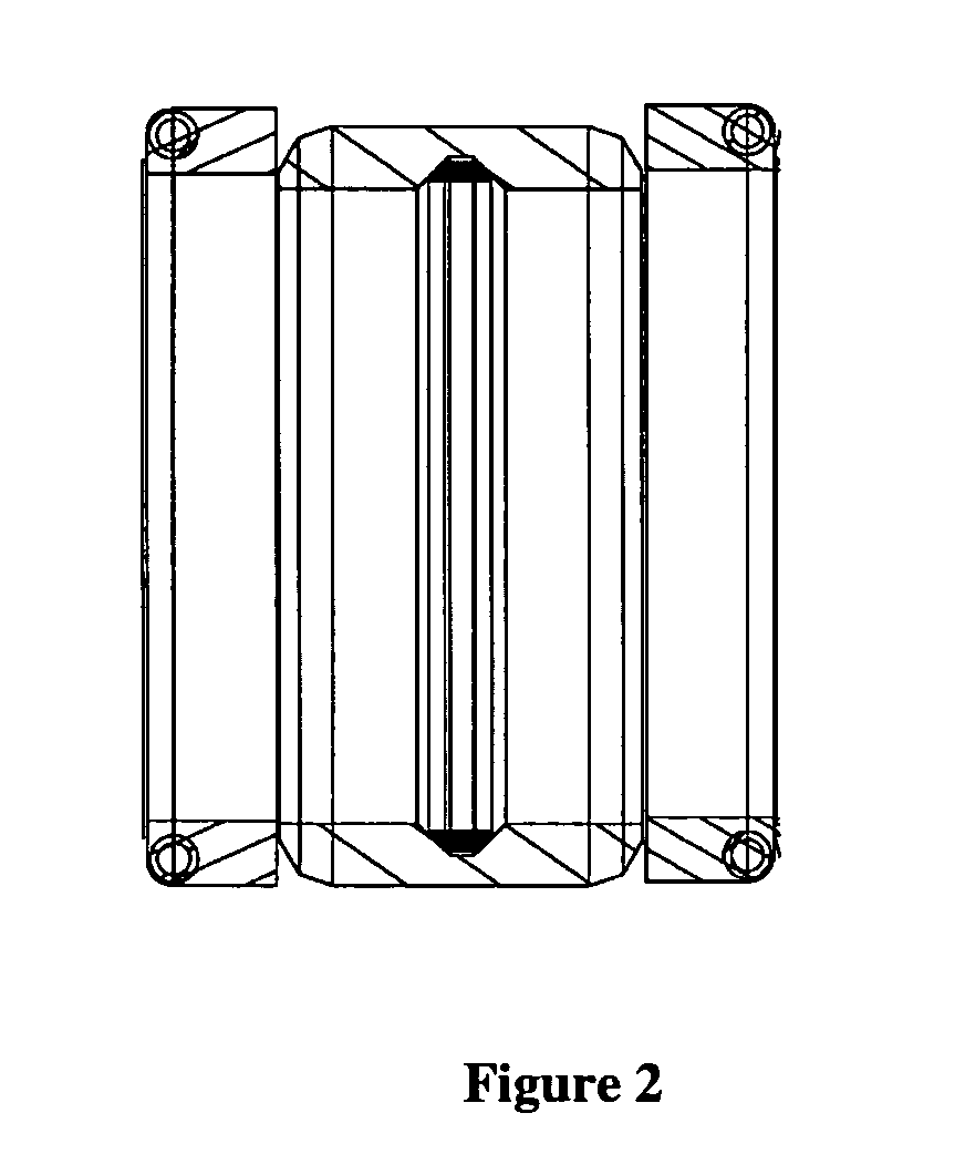
[0031]FIG. 2 shows a garter spring element array 50. The array 50 includes a main element or seal body 52, a garter spring 54 and backup end rings 56. The array also includes an ID ring 58. Hydrogel may be included in any or all of the seal b...

example 2

O-Ring

[0033] O-rings are simple bi-directional static seal bodies. For high temperature and / or high pressure sealing applications, backup rings are used to prevent O-ring extrusion. As shown in FIG. 4, the o-ring 150 includes two backup rings 152 which are formed of thermoplastic materials blended with hydrogel polymer. The O-ring may also be formed of elastomers blended with hydrogel polymer. In this application, the hydrogel is able to seal off potential leak paths as well as keep the o-ring energized via swelling. These characteristics are not achievable with existing conventional rubber materials used for o-ring applications.

example 3

T-Seal Bodies

[0034] T-seal bodies are typically used as reciprocating bi-directional dynamic seals. As shown in FIG. 5, T-seal 200 including seal body 202 and retaining ring 204. The seal body is formed of a hydrogel modified thermoplastic or elastomer. Hydrogel can seal off potential leak paths as well as keep the T-seal energized via swelling. These benefits are not achievable with existing conventional rubber materials used for T-seal application.


PUM

PropertyMeasurementUnit
temperatureaaaaaaaaaa
weightaaaaaaaaaa
sealing forcesaaaaaaaaaa

Abstract

The present invention is a composition for forming seals. The composition includes a base material and a hydrogel. The base material is preferably an elastomer or a thermoplastic. Seals formed with the composition are particularly suited for use in a wellbore environment. The inclusion of hydrogel in the seals allows the seals to be manipulated or altered through certain environmental factors. For instance, temperature, oil / water ratio, pH and the electronic field may all be used to alter the characteristics of the hydrogel. In this way, the seal may be caused to swell in response to a specific stimulus, thereby preventing or sealing a leak without requiring additional work or input from the operator.

Description

CROSS REFERENCE TO RELATED APPLICATION [0001] This application claims the benefit of U.S. Provisional Application Ser. No. 60 / 541,035, filed on Feb. 2, 2004, and is a Continuation-In-Part of and also claims the benefit of U.S. patent application Ser. No. 10 / 789,846, filed on Feb. 27, 2004.BACKGROUND OF THE INVENTION [0002] 1. Field of the Invention [0003] The present invention relates generally to seals for oilfield applications. More specifically the present invention describes the use of hydrogel in seal bodies for downhole use. [0004] 2. Description of the Prior Art [0005] Seal bodies, including o-rings, packer elements, Chevron seals, gaskets, etc., are widely used for numerous downhole oilfield applications. One ongoing issue in this area is how to energize seals and maintain sealing forces throughout seal service life. Capital loss or remediation associated with seal failure can be tremendous in certain operation areas. [0006] One conventional method to energize seals is to ut...

Claims


Application Information

Patent Timeline
Patent Type & Authority Applications(United States)
IPC IPC(8): C08L1/00C08L1/28C08L5/14C09K3/10E21B33/12
CPCC08L1/28C08L5/14C08L101/00C08L101/14C09K3/10C09K2200/06C09K2200/0617E21B33/12C09K2200/0627C09K2200/0632C09K2200/0657C09K2200/0685C08L2666/06C08L2666/02C08L2666/08C08L2666/26
Inventor LI, YANMEIZHOU, JIAN
Owner SCHLUMBERGER TECH CORP
Why Eureka
Try Eureka