[0011] The present invention relates to modules, such as modules with elements or components used in heat exchange, particularly for vehicles, such as motorized or automotive vehicles. So called ‘engine cooling’ modules or ‘front end modules’ or carriers or bolsters, in accordance with the present invention, further comprise elements or components, often used in assemblies useful for efficient heat exchange, particularly suited for automotive or
motorized vehicle fluid or liquid circulating or cooling systems. In preferred aspects of the present invention, a
bottle or reservoir is provided that has, as a
dual function, storage of a liquid or fluid and, in particular, a fluid capable of heat exchange (fluid reservoir), while allowing improved overall or more efficient cooling by the module or
assembly. Also this invention covers the
scenario where more than one fluid are handled through reservoirs which are separately integrated or made of multiple separated chambers of the reservoir. The present invention, by providing for both functions in a single module or
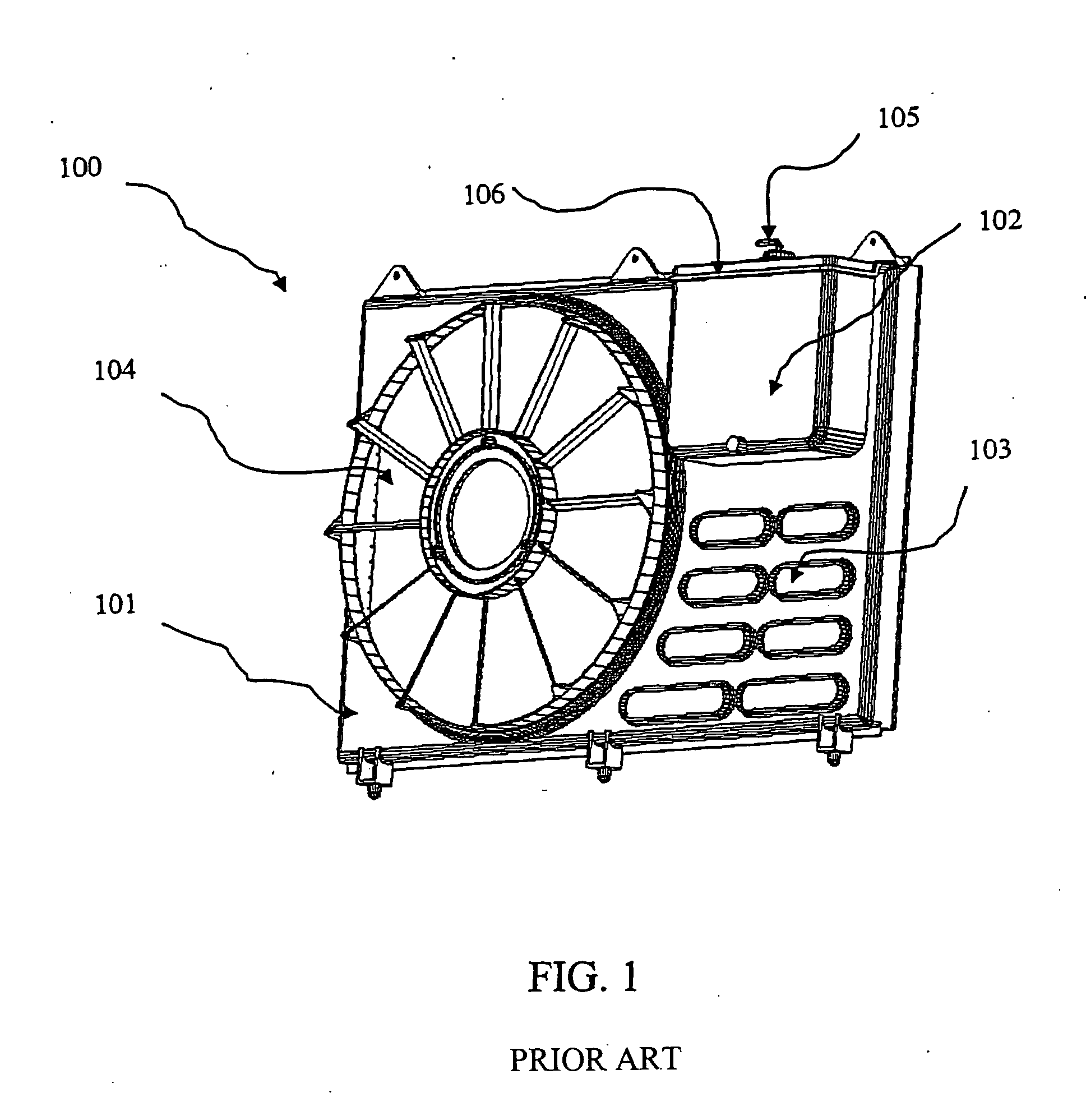
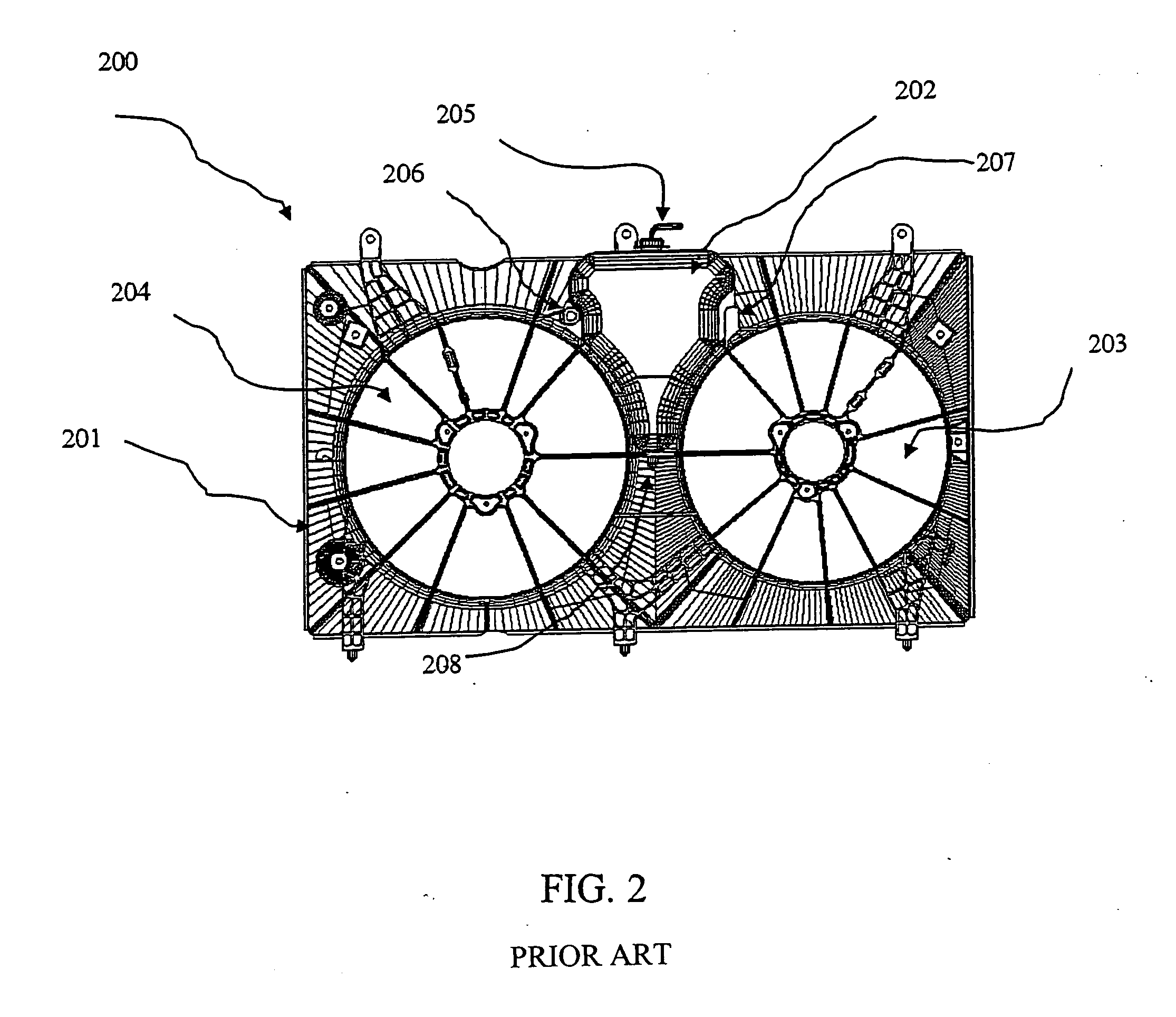
assembly, leads to cost benefits over prior art
bottle and shroud or similar combinations.
[0012] In preferred aspects of the present invention, a reservoir, chamber,
bottle or the like (fluid reservoir) is provided as an integrated or separate part of an
assembly and / or module, such as an engine cooling or front end module or
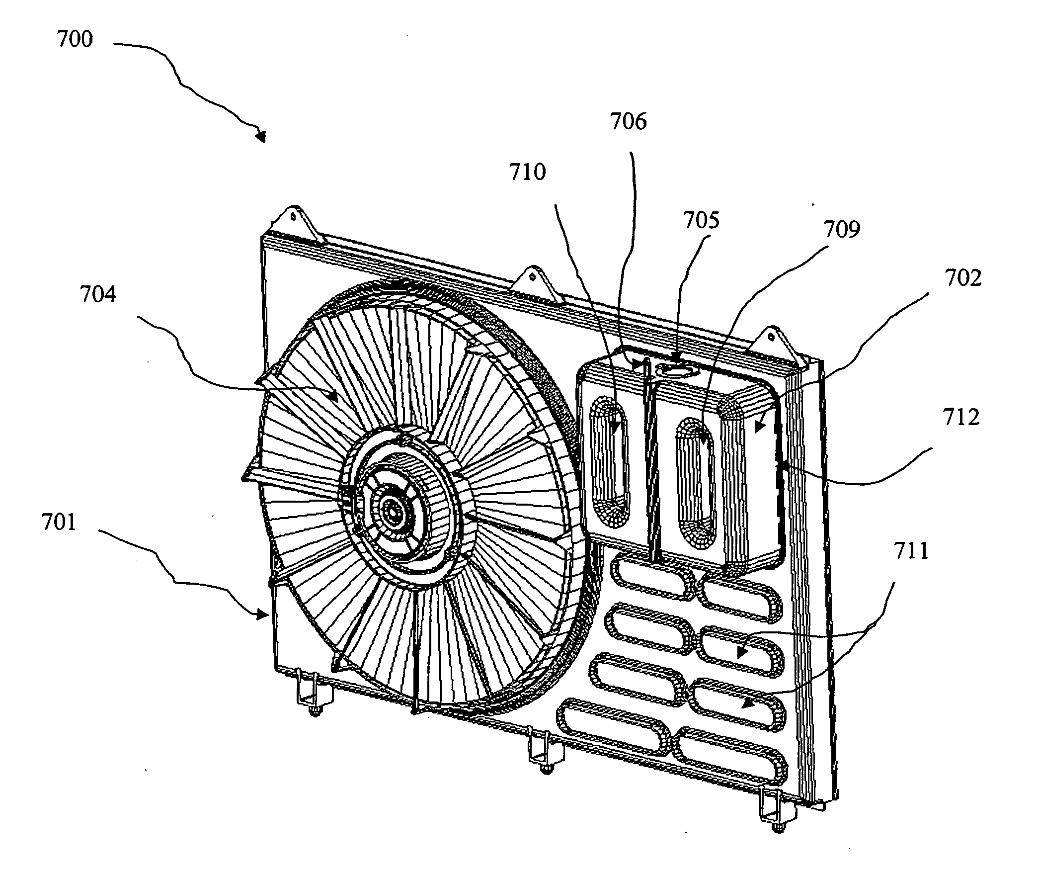
bolster. Preferably the fluid reservoir has at least one opening (slot). The fluid reservoir maintains its fluid(s) within its confines or walls. In the present invention, an area or zone of the walls of the fluid reservoir is constructed so as to form at least one passageway or opening in the fluid reservoir (slot) where air can pass through the fluid reservoir without contacting the fluid therein. Preferably, the fluid reservoir has two or more slots at areas or zones where the reservoir is exposed to the exterior environment or outside air at the exterior surface of the reservoir and exposed to the fluid inside on the interior surface of the reservoir. Preferably, at least one or two or more holes or opening(s) (slot(s)) is a through slot, i.e., the slot allows for air to pass or flow from the front or initial air flow contact area of the fluid reservoir to the opposite, back or posterior side of the fluid reservoir, front and back being determined by the placement of the fluid reservoir in the module and the direction of air flow in the normal environment of the engine cooling module or
system. In preferred embodiments, since the air normally passes or flows over or is pushed or pulled through from the anterior or front end of the automobile to the posterior or back end of the vehicle, the fluid reservoir is placed such that the air can pass or flow, be pushed or pulled through the slot or slots in the fluid reservoir under normal vehicle operation conditions, from one side to the other of the reservoir in such as fashion that the fluid reservoir preserves the function of bottle as a reservoir (maintaining fluids within without leakage or outside contact) while also allowing for improved cooling. By providing for through slots through the fluid reservoir for air passage, air flow that normally would be blocked or stopped by certain elements associated with other modules or assemblies of the vehicle, such as, for example, bolsters, shrouds or the like in a fan assembly in a vehicle, is no longer blocked and can pass or flow over or ‘through’ areas or zones of the fluid reservoir previously inaccessible in prior art vehicles. The present invention provides, therefore, for air to pass or flow through areas wherein previously inefficient, practically inexistent or inappropriate heat exchange could occur or dead zones, thereby increasing the heat exchange capacity of the entire module.
[0013] In particularly preferred embodiments, the presence of such through slots, and, in particular, slots formed by partitions or divisions in the fluid reservoir forming chambers or sections, in the fluid reservoirs can be especially important. For example, preferred embodiments of the present invention allow for air to get through to areas where efficient heat exchange can occur, particularly when the vehicle is moving at high speeds, that would not be achievable due to conditions such as fan ‘block’; minimalized passage due to reservoir ‘block’ wherein there are no through slots or openings; or wherein the fan output cannot keep up with the desired exchange of air over the heat exchange surface of the
heat exchanger alone due to the increase volume and / or velocity of air passage. By having the reservoir, and, in particular, one or more slots of the reservoir, partially aligned, or, preferably, in at least 50% alignment, with and, even more preferably, at least between 70-100% aligned with at least one opening in the shroud or other modular part, simplicity, lower cost and improved
system performance and competitiveness occur over current solutions. The slot or, preferably, slots, can be of practically any shape, such as round, square, oval, rectangular, triangular or any other shape or modification of one of the basic shapes.

