
Print system printing data while storing under compressed state, and printer for use therein

a printing system and compressed state technology, applied in the direction of printing units, instruments, digital output to print units, etc., can solve the problem of reducing the capacity of dot data

Inactive Publication Date: 2006-03-09
SEIKO EPSON CORP
View PDF1 Cites 6 Cited by
  • Summary
  • Abstract
  • Description
  • Claims
  • Application Information

AI Technical Summary

Benefits of technology

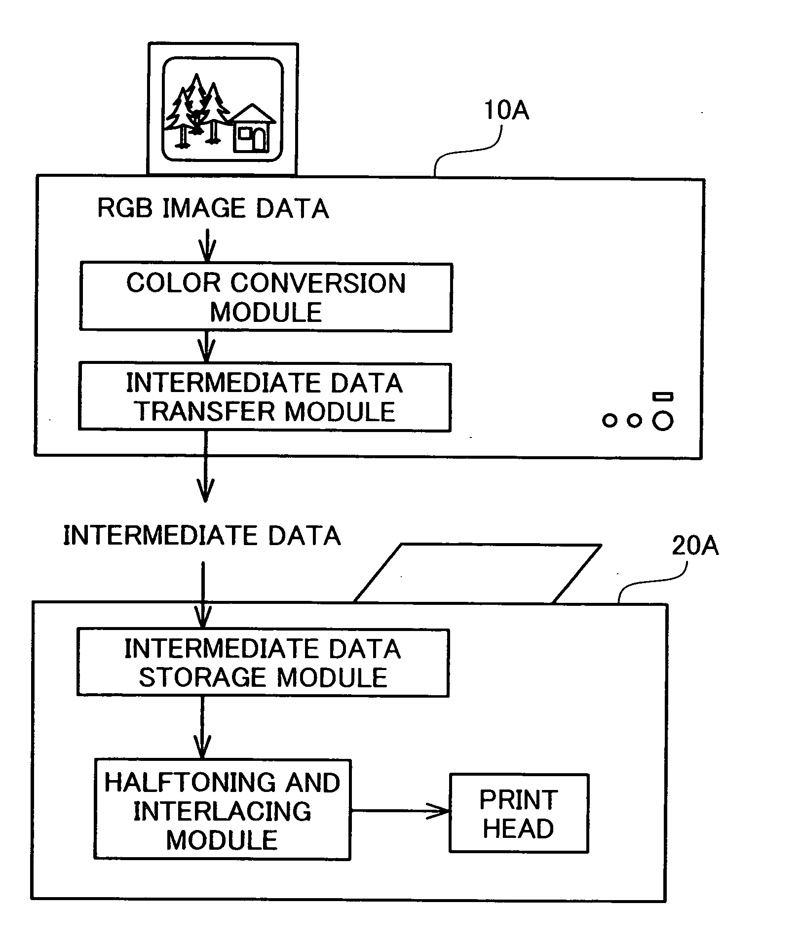
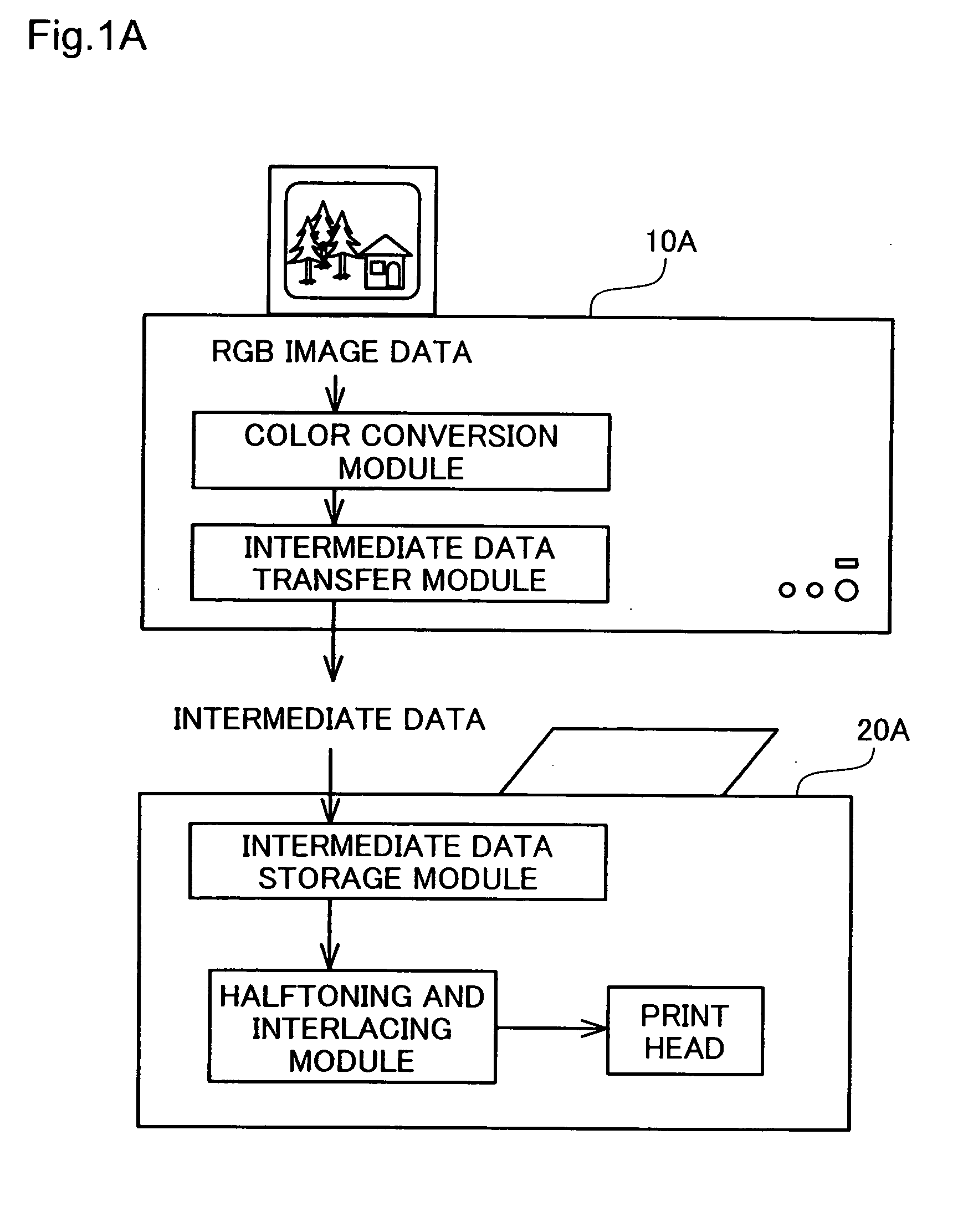
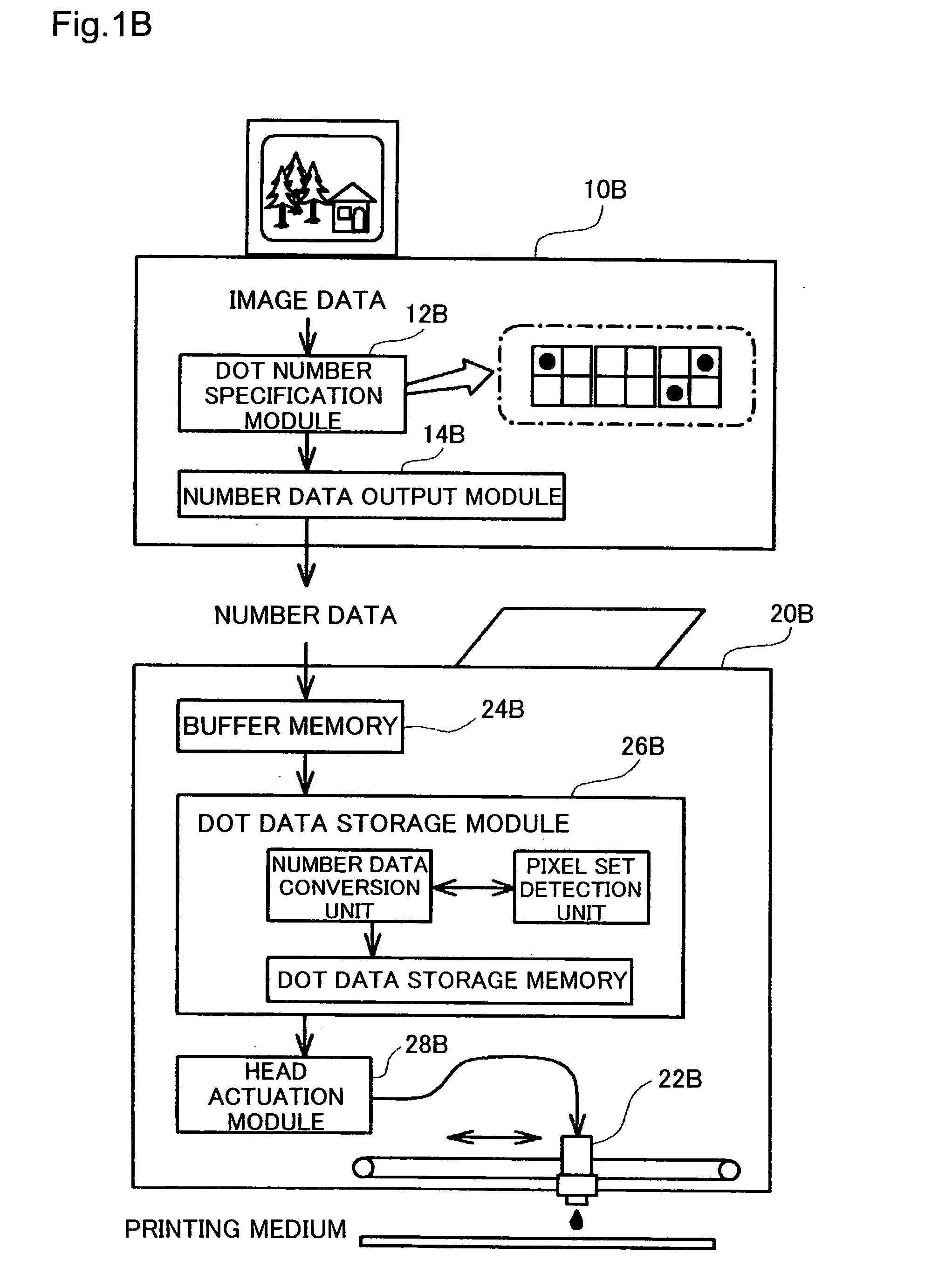
[0058] In order to describe the functions and the effects of the invention clearly, some modes of carrying out the invention are discussed below in the following sequence: [0059] A1. Mode of Carrying Out the Invention—1 [0060] A2. Mode of Carrying Out the Invention—2 [0061] B. Construction of Device in Embodiment [0062] C. General Flow of Image Processing in First Embodiment [0063] D. Halftoning and Interlacing Process [0064] E. Modification [0065] F. General Flow of Image Processing in Second Embodiment [0066] G. Number Data Generation Process [0067] H. Number Data Decoding Process
[0062] C. General Flow of Image Processing in First Embodiment
[0065] F. General Flow of Image Processing in Second Embodiment

Problems solved by technology

This arrangement thus reduces the capacity of the dot data.

Method used


Image

  • Print system printing data while storing under compressed state, and printer for use therein
  • Print system printing data while storing under compressed state, and printer for use therein
  • Print system printing data while storing under compressed state, and printer for use therein

Examples


first embodiment

[0082]FIG. 3 schematically illustrates the structure of the color printer 200 in the The color printer 200 is an inkjet printer that is capable of creating four color ink dots, cyan, magenta, yellow, and black. The color printer 200 may alternatively be an inkjet printer that is capable of creating six color ink dots including cyan ink having a low dye density (light cyan ink) and magenta ink having a low dye density (light magenta ink), in addition to the above four color inks. In the description below, cyan ink, magenta ink, yellow ink, and black ink are referred to as C ink, M ink, Y ink, and K ink.

[0083] As illustrated, the color printer 200 has a mechanism of actuating a print head 241 mounted on a carriage 240 for ink ejection and dot creation, a mechanism of activating a carriage motor 230 to move the carriage 240 back and forth along an axis of a platen 236, a mechanism of activating a paper feed motor 235 to feed printing paper P, and a control circuit 260 that controls do...

second embodiment

[0145] F. Outline of Image Processing in Second Embodiment

[0146] A second embodiment of the invention is described below. The printing system of the second embodiment corresponds to the mode shown in FIG. 1B and has the hardware construction identical with that of the first embodiment. In the second embodiment, the control data used for controlling ejection of ink droplets are generated by a series of image processing of an object image to be printed. FIG. 15 is a flowchart showing a process of generating control data and printing an image (image printing process). As described below, in this embodiment, the first half of the image printing process is executed by the CPU built in the computer 100, while the latter half of the image printing process is executed by the CPU built in the control circuit 260 of the printer 200. The outline of the image printing process is described below according to the flowchart of FIG. 15.

[0147] When the image printing process starts, the computer 10...


PUM


Abstract

In a printing process with a print head having multiple dot formation elements for creating dots, an overlap printing technique that uses at least two dot formation elements for formation of each raster line requires a large memory capacity for storage of dot data. In a printing system of the invention, an image processing device takes charge of a former part of image processing and outputs intermediate data in a state requiring expansion into multiple pixels to a printing device. The printing device expands intermediate data including a target pixel, for which a dot on-off state is to be specified, and specifies the dot on-off state in the target pixel based on the intermediate data. Every time the dot on-off state is specified in each target pixel, intermediate data including the target pixel is expanded. This arrangement does not require the printing device to have a large storage capacity for the image processing. The printing device and the image processing device can thus effectively share the series of image processing, even when the printing device has a small storage capacity and low processing power.

Description

TECHNICAL FIELD [0001] The present invention relates to a technique of making an image subjected to a preset series of image processing and printing the processed image. More specifically the invention pertains to a technique of causing an image processing device and a printing device to share the preset series of image processing and print the processed image. BACKGROUND ART [0002] Printing devices that create dots on a printing medium to print an image are widely used as the output device of various imaging devices. In these printing devices, an image is divided into tiny areas called pixels, and dots are created in these pixels. Such a printing device takes only either of two states, a dot-on state and a dot-off state, in each pixel, but makes areas of dense dot creation and areas of sparse dot creation in the whole image. For example, in the case of creation of blank ink dots on printing paper, areas of dense dot creation are dark areas and areas of sparse dot creation are brigh...

Claims


Application Information

Patent Timeline
Patent Type & Authority Applications(United States)
IPC IPC(8): B41C1/04G06K15/10
CPCG06K15/105
Inventor KAKUTANI, TOSHIAKI
Owner SEIKO EPSON CORP
Learn More