Illuminating device

a technology of illumination device and liquid crystal element, which is applied in the direction of lighting and heating equipment, instruments, display means, etc., can solve the problems of high manufacturing cost, high risk of operation failure, and complicated structure of such illumination device, and achieve the effects of enhancing luminosity, reducing production cost, and uniform illumination of liquid crystal elements

Inactive Publication Date: 2006-03-09
NANOGATE ADVANCED MATERIALS
View PDF14 Cites 28 Cited by
  • Summary
  • Abstract
  • Description
  • Claims
  • Application Information

AI Technical Summary

Benefits of technology

[0031] Known display or liquid crystal elements according to prior art comprise a light element, such as a light box. A plurality of fluorescent tubes, in particular CCFLs, are arranged as light sources in the light element. To make the light emitted by the fluorescent tubes more uniform and thus to make the illumination of the liquid crystal element more uniform, foils are arranged between the fluorescent light tubes and the liquid crystal element. These foils are so-called BEF and DBEF Foils, respectively. A BEF foil is to enhance luminosity. This is achieved by providing a plurality of prisms on the foil. The DBEF foil is used to change the polarity of the light reflected from the rear side of the liquid crystal element and to return the light back towards the liquid crystal element. Further, PRF foils are used to change the polarity. Providing such foils, however, has the drawback that the foils absorb a part of the light.
[0032] In the present flat display, the BEF foil and preferably also the DBEF foil and the PDF foil are replaced with the light guide member configured according to the invention. Preferably, a plurality of light tubes, such as CCFLs, are provided. A light guide member according to the invention is arranged in front of the light tubes, which, as described above, comprises a plurality of surface elements or groups of surface elements. It is particularly preferred that the light guide member has one zone per light tube, which zone is arranged preferably in parallel with the light tube and has a plurality of surface elements or groups of surface elements. Here, the individual zones may be identical in configuration. Thus, production costs can be reduced.

Problems solved by technology

The structure of such illuminating devices is complicated, the more so, since a plurality of films have to be placed into a frame or the like, for example, and it has to be ensured that a slipping or the like of the films is avoided.
Due to the complicated structure, the manufacturing costs are high.
Moreover, there is a risk of operational failures.
Making such a surface structure with different grating amplitudes is extremely difficult.
Further, due to the immediate contiguity of the individual gratings, it is likely that diffraction effects that are hard to predict, such as undesired interferences, for example, because of the precision technically difficult to obtain.

Method used


Image

  • Illuminating device
  • Illuminating device
  • Illuminating device

Examples


Embodiment Construction

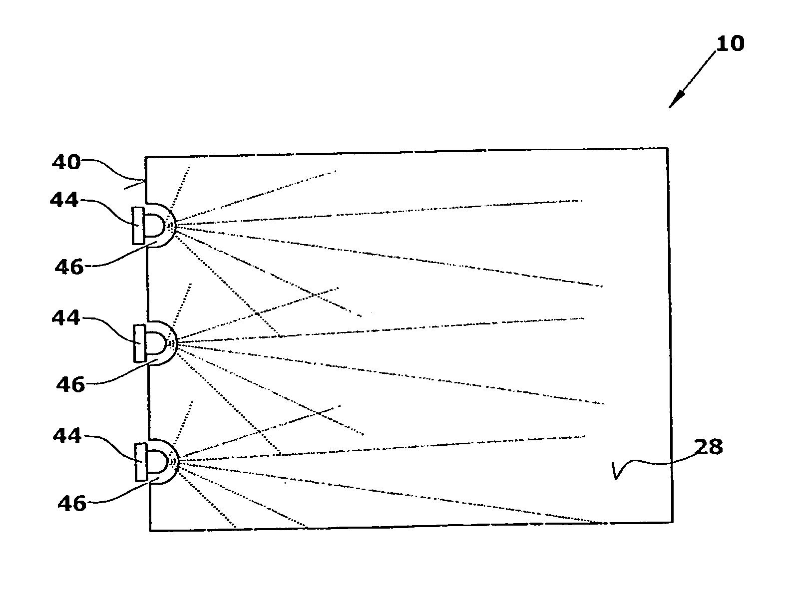
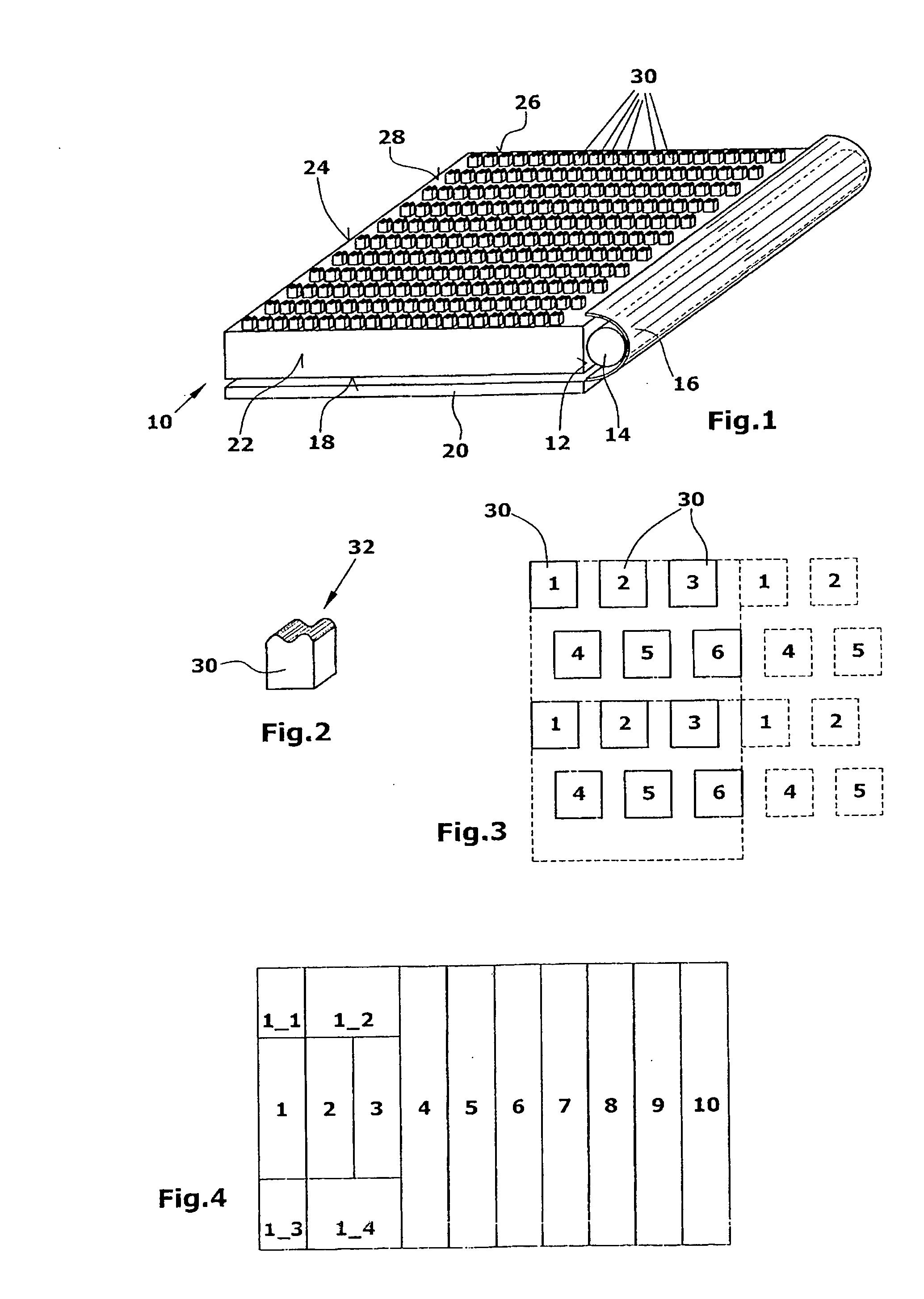
[0047] The present illuminating device comprises a light guiding member 10 that is cuboid in the embodiment illustrated and may be made, for example, of a transparent resin or a plastic material such as PPMA or the like. In the embodiment shown, a rod-shaped light source is arranged along one side face 12 of the light guiding member 10, the longitudinal axis of the light source 14 being arranged in parallel to the side face 12. The light source 14 is surrounded by a parabolic reflector 16, whose open side is directed towards the side face 12. Thus, the amount of light coupled into the side face 12 is augmented. The light source 14, which may be a plurality of LEDs instead of the light tube shown, preferably has a light density in the range from 20,000-50,000 cd / m2. When providing a tubular light source 14, the same is preferably arrange in the focal axis of the parabolic reflector 16.

[0048] The bottom face 18 of the light guiding member 10 is provided with a reflector 20 which may ...


PUM


Abstract

An illuminating device for backlighting flat displays, in particular displays for mobile applications, is provided. The illuminating device includes a light source and a light guiding member into which light emitted from the light source is coupled in and is coupled out therefrom at an exit surface. The exit surface has a surface structure including diffractive surface elements for light propagation, wherein all surface elements have a surface structure with a constant amplitude.

Description

CROSS-REFERENCE TO RELATED APPLICATIONS [0001] This application claims the benefit under 35 U.S.C. § 119 of U.S. Provisional Application Ser. No. 60 / 644,879 filed on Jan. 18, 2005, European Patent Application No. 04 021 429.8 filed on Sep. 9, 2004, European Patent Application No. 05 100 313.5 filed on Jan. 19, 2005, and European Patent Application No. 05 005 303.2 filed on Mar. 10, 2005, the entire contents of all of which are incorporated by reference herein.BACKGROUND OF THE INVENTION [0002] 1. Technical Field [0003] The invention refers to an illuminating device for backlighting flat displays, in particular displays for mobile applications. [0004] 2. Related Prior Art [0005] Known illuminating devices for displays for mobile applications comprise a light source, which may be a tubular light source (CCFL), for example. The light emitted from the light source is coupled into a light guiding member of wedge-shaped cross section at an end face thereof. Specifically because of the wed...

Claims


Application Information

Patent Timeline
Patent Type & Authority Applications(United States)
IPC IPC(8): F21V7/04
CPCG02B6/0021G02B6/0068G02B6/0036
Inventor STADTWALD-KLENKE, MARTIN
Owner NANOGATE ADVANCED MATERIALS
Why Eureka
Try Eureka