Heating apparatus and image forming apparatus

a technology of image forming apparatus and heating apparatus, which is applied in the direction of electrographic process apparatus, instruments, optics, etc., can solve the problems of systematically overlapping or binding the output recording media, extreme curl, and warp and curl in the recording medium, so as to prevent the curl of the output recording member and prevent the curl

Active Publication Date: 2006-03-09
CANON KK
View PDF13 Cites 23 Cited by
  • Summary
  • Abstract
  • Description
  • Claims
  • Application Information

AI Technical Summary

Benefits of technology

[0026] Therefore, it is an object of the present invention to provide a heating apparatus capable of restraining the curl of an output member to be heated and an image f...

Problems solved by technology

Therefore, contraction and expansion values are changed at the front surface and back surface of the recording medium and there is a problem that warp and curl occur in the recording medium after fixed.
Particularly, when the environment in which an image forming apparatus or recording medium is put is a high-humidity environment and the recording medium contains much moisture and lacks in thickness and rigidity, curl becomes extreme.
When curl becomes extreme, it is impossible to systematically overlap or bind output recording media and the convenience of the...

Method used


Image

  • Heating apparatus and image forming apparatus
  • Heating apparatus and image forming apparatus
  • Heating apparatus and image forming apparatus

Examples


first embodiment

(1) An Example of an Image Forming Apparatus

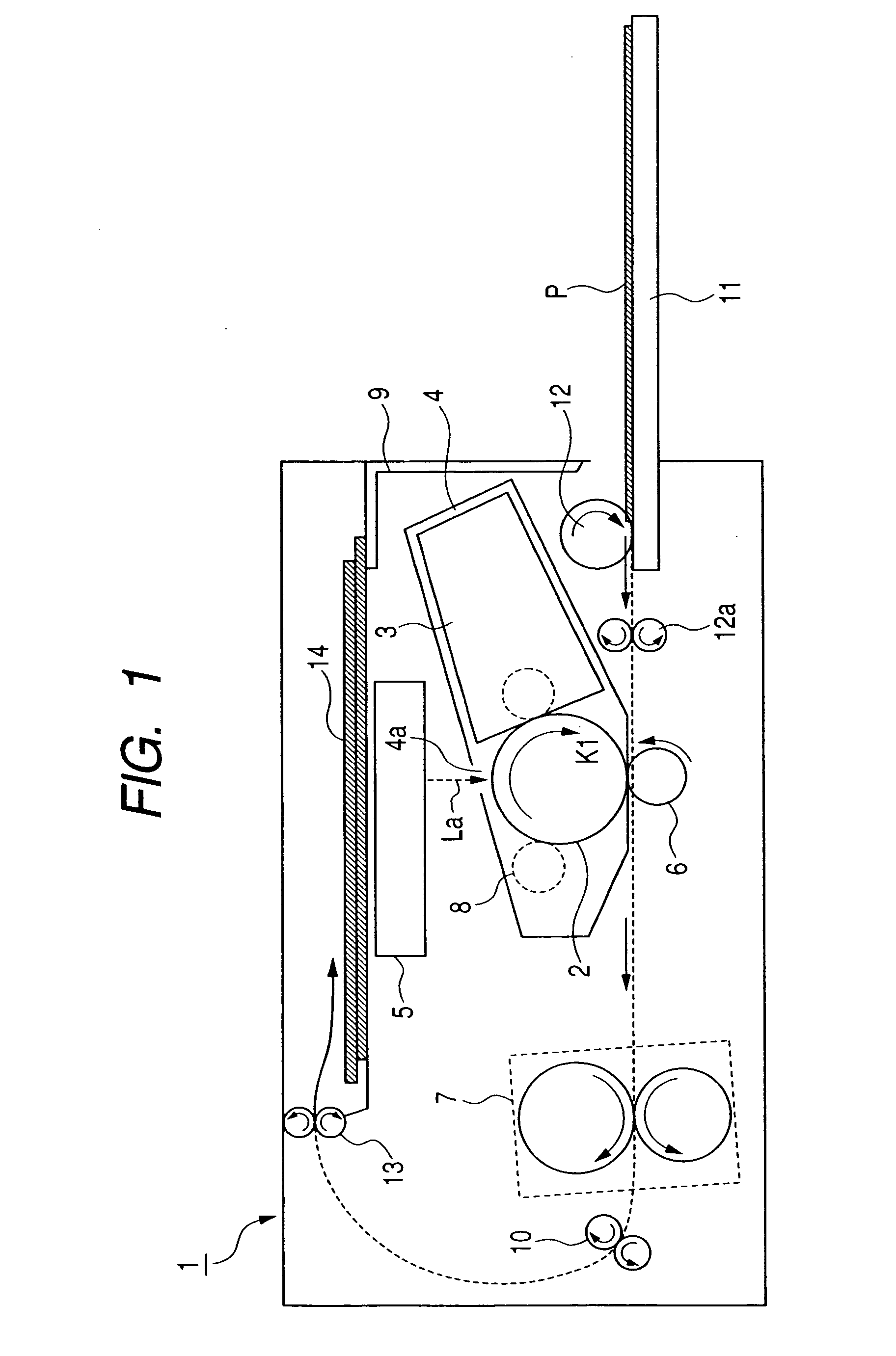
[0068]FIG. 1 is a schematic sectional view showing a schematic configuration of a laser beam printer (hereafter referred to as printer) 1 which is an example preferably showing the image forming apparatus of this embodiment.

[0069] The printer 1 is an image forming apparatus for performing a series of image forming processes of forming an image corresponding to the image information supplied from an external image-information providing apparatus (not illustrated) such as a host computer on a sheet-type recording medium P and recording the image in accordance with the widely-known electrophotographic system.

[0070] The printer 1 has a process cartridge 4 for holding a drum-type rotatable electrophotographic photosensitive member 2 serving as a latent image carrying body and a developing apparatus 3, a laser scanner unit (hereafter referred to as scanner) 5 for forming an electrostatic latent image by exposing the outer periphery of the ph...

second embodiment

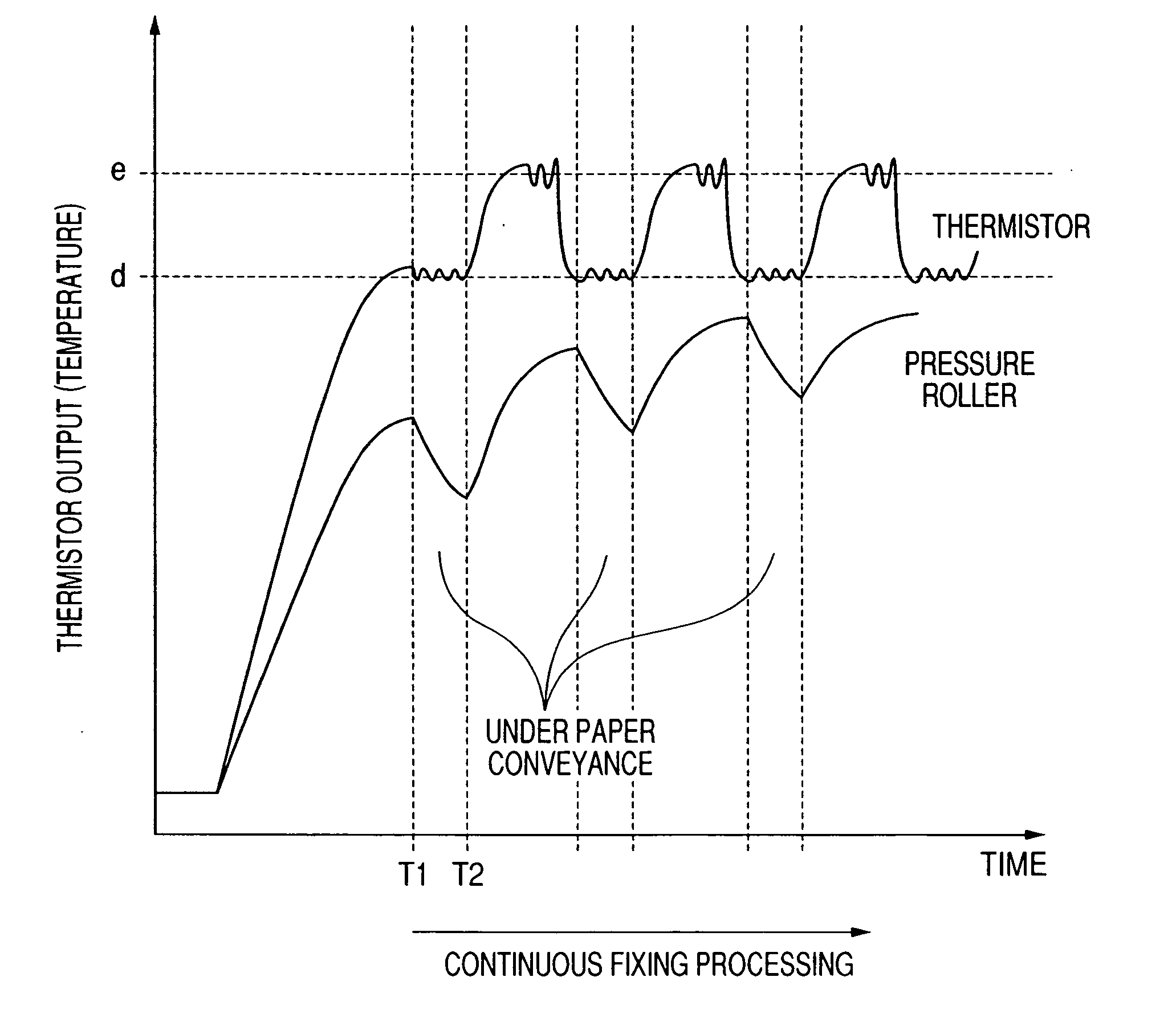
[0148] A schematic configuration of the image forming apparatus of this embodiment is the same as the case of the embodiment 1. As shown in FIG. 10, recording-medium water-content detection means 27 for detecting the water content of a recording medium is used and power control means 24 changes the difference between the paper conveyance interval temperature e and the fixing temperature d and a paper conveyance interval length in accordance with the water content of the recording medium detected by the water-content detection means 27.

[0149] The electrical analog information on the recording-medium water content detected by the water-content detection means 27 is input to an analog-digital conversion circuit (A / D conversion circuit) 28 and digitized and input to the power control means 24.

[0150] The water-content detection means 27 of the recording medium P includes the electric resistance type, high-frequency resistance type, high-frequency capacity type and microwave type and it...

third embodiment

[0162] A schematic configuration of the image forming apparatus of this embodiment is the same as the case of the embodiment 1. As shown in FIG. 11, this embodiment is provided with environment detection means 29 for detecting the temperature or humidity of the environment in which the image forming apparatus is set or both of the temperature and humidity and power control means 24 changes the difference between the paper conveyance interval temperature e and the fixing temperature d and a paper conveyance interval length in accordance with a detection result by the environment detection means 29.

[0163] Electrical analog information on the temperature or humidity of the environment detected by the environment detection means 29 or both of the temperature and humidity is input to an analog-digital conversion circuit (A / D conversion circuit) 30, digitized and input to the power control means 24.

[0164] A sheet used for an image forming apparatus set in a high-temperature high-humidit...


PUM


Abstract

The heating apparatus has a heating member and a pressure member which are mutually pressure-welded to hold and convey and heat a heated member to be heated by a nip portion formed between the heating member and the pressure member, includes a temperature detector, power control means, and a curl reduction mode for setting a paper conveyance interval temperature which is the target temperature of the heating member set in a paper conveyance interval which is a period from end of heating the M-th member to be heated up to start of heating the M+1-th member to be heated in continuous heating of N members to be heated or in a certain period in the paper conveyance interval to a temperature higher than the heating temperature of a member to be heated which is the target temperature of the heating member when heating the M+1-th member to be heated.

Description

BACKGROUND OF THE INVENTION [0001] 1. Field of the Invention [0002] The present invention relates to a heating apparatus for heating a conveyed and introduced material to be heated at a heating portion and discharging the material. [0003] More particularly, the present invention relates to a heating apparatus having mutually-pressure-welded heating member and pressure member to hold and convey a member to be heated by a nip portion formed between the heating member and the pressure member and heat the member to be heated. [0004] Moreover, the present invention relates to an image forming apparatus such as a printer or copying machine having the heating apparatus as an image heating and fixing apparatus. [0005] 2. Description of Related Art [0006] Hereafter, as an example, a fixing apparatus serving as a heating apparatus for heating and fixing an image in an image forming apparatus is described below. [0007] A general fixing apparatus heats and pressure-fixes an unfixed image on a r...

Claims


Application Information

Patent Timeline
IPC IPC(8): G03G15/20
CPCG03G2215/2035G03G15/2046
Inventor NISHIDA, SATOSHI
Owner CANON KK
Why Eureka
Try Eureka