Upright bent edge structure of a striking plate for combing with a golf club head body

a striking plate and bent edge technology, applied in the field of upright bent edge structure of striking plates, can solve the problems of increasing manufacturing costs, deteriorating elastic deformation of striking plates, and large number of unqualified golf club heads in manufacture, and achieve the effect of increasing design choi

Inactive Publication Date: 2006-03-09
NELSON PRECISION CASTING
View PDF14 Cites 30 Cited by
  • Summary
  • Abstract
  • Description
  • Claims
  • Application Information

AI Technical Summary

Benefits of technology

[0012] The primary objective of this invention is to provide an upright bent edge structure of a striking plate for combining with an assembling reces...

Problems solved by technology

On the one hand the braze welding process for the golf club head may increase manufacture cost, and on the other hand it may deteriorate elastic deformation of the striking plate due to directly connecting an annular edge of the striking plate to an inner edge of the assembling recession.
However, there exist several drawbacks of golf club head disclosed in TWN552988.
Also, it may cause the welding machine a specific deviation for positioning the golf club head and result in a large number of unqualified golf club heads in manufacture.
Namely, if th...

Method used


Image

  • Upright bent edge structure of a striking plate for combing with a golf club head body
  • Upright bent edge structure of a striking plate for combing with a golf club head body
  • Upright bent edge structure of a striking plate for combing with a golf club head body

Examples


Embodiment Construction

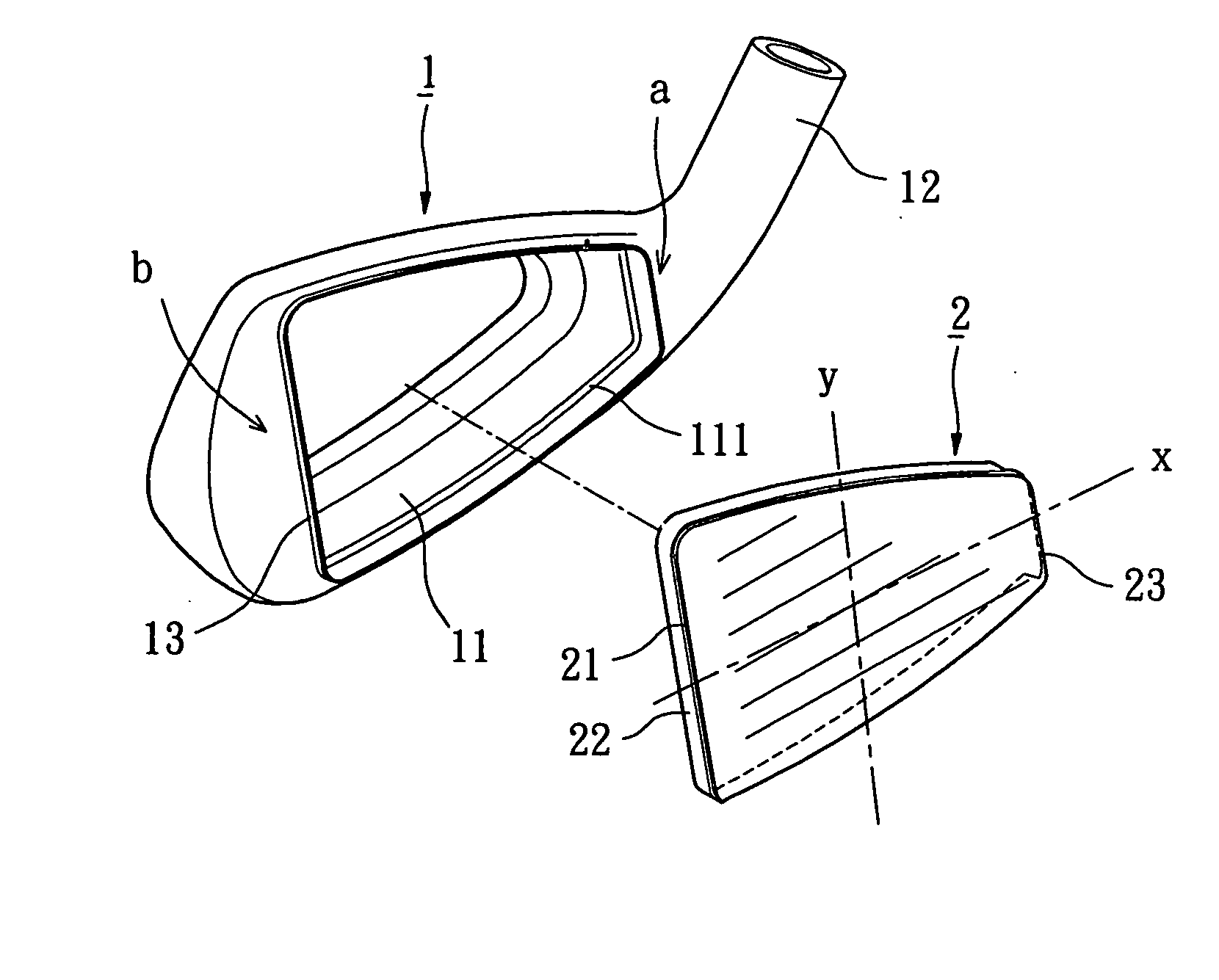
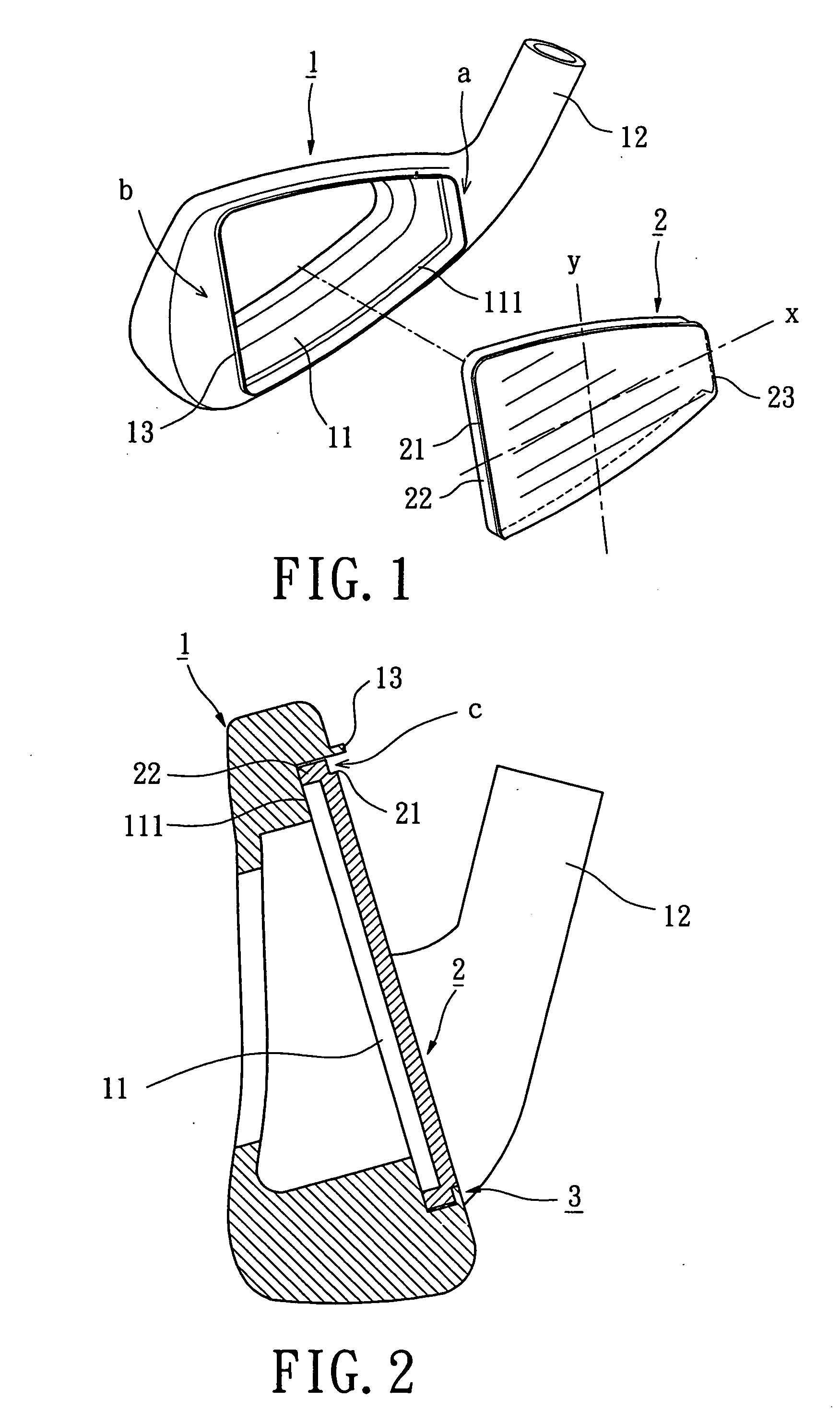
[0029] Referring initially to FIGS. 1 and 2, a golf club head in accordance with a first embodiment of the present invention generally includes a golf club head body member designated numeral 1 and a striking plate member designated numeral 2.

[0030] Referring again to FIG. 1, the construction of the golf club head body 1 shall be described in detail. The golf club head body 1 is made of stainless steel, carbon steel, alloy steel or Fe—Mn—Al alloy by casting, forging or mechanically pressing. The golf club head body 1 includes an assembling recession 11, a hosel 12 and an engaging protrusion 13. The golf club head body 1 forms the assembling recession 11 at its front side while selectively forming a sealing member or an opening at its rear side. The hosel 12 is used to securely receive an end of a shaft (not shown). The assembling recession 11 provides with a shoulder 111 extending on an inner surface.

[0031] The golf club head body 1 further includes a heel portion as indicated at ...


PUM


Abstract

A golf club head includes a golf club head body, a striking plate and a connecting portion. The golf club head body provides with an assembling recession at its front side. The striking plate provides with a main plate, an upright bent edge and a support wall to constitute a U-shaped or L-shaped configuration that can increase elastic deformation of the striking plate. In assembling, the support wall of the striking plate is initially inserted into the assembling recession of the golf club head body. The connection portion is located between the golf club head body and the striking plate, and securely connects the striking plate with the golf club head body.

Description

BACKGROUND OF THE INVENTION [0001] 1. Field of the Invention [0002] The present invention relates to an upright bent edge structure of a striking plate for combining with a golf club head body. More particularly, the present invention relates to a U-shaped or L-shaped bent edge structure of a striking plate employing a connecting portion adapted to combine the striking plate with a golf club head body. Thereby, the upright bent edge structure of the striking plate enhances striking characteristic and connecting quality for different metals. [0003] 2. Description of the Related Art [0004] Two conventional connecting methods for combining a striking plate with a golf club head is disclosed in Taiwanese Patent Publication Nos. 469,143 and 552,988. [0005] First, TWN469143 discloses a golf club head body and a striking plate connected thereto. The golf club head body includes an assembling recession at its front side. In assembling, the assembling recession of the golf club head body acc...

Claims


Application Information

Patent Timeline
IPC IPC(8): A63B53/04
CPCA63B53/04A63B53/047A63B2053/0462A63B2053/0458A63B2053/0416A63B53/0458A63B53/0462A63B53/0416A63B60/00
Inventor HOU, WEN-CHING
Owner NELSON PRECISION CASTING
Why Eureka
Try Eureka