
Method and apparatus for automatically disinfecting plumbing fixtures

a technology for automatic disinfection and plumbing fixtures, applied in the field of plumbing fixtures, can solve the problems of difficult to completely drain all of the water, inaccessible plumbing, and nearly impossible to prevent standing water from being left in the plumbing

Inactive Publication Date: 2006-03-16
CEG HLDG
View PDF9 Cites 15 Cited by
  • Summary
  • Abstract
  • Description
  • Claims
  • Application Information

AI Technical Summary

Benefits of technology

[0010] One object of the present invention is to provide an improved whirlpool bath system. Relate

Problems solved by technology

Specifically, there is a concern that it is difficult to completely drain all of the water from the whirlpool circulation plumbing, resulting in an environment conducive to the growth of bacteria and fungi.
Since the plumbing is principally located outside of the bathtub (and is usually covered), the plumbing is generally inaccessible without undertaking the major effort of disassembling and removing the tub itself.
The inaccessibility of the plumbing makes it nearly impossible to prevent standing water from being left therein after each use of the whirlpool bath.
This is a problem because the standing water typically includes residual soap scum, scale deposits, sloughed off skin cells, body oils and other fluids, fecal matter, and other bathing residue.
The situation worsens in the case of publicly used fixtures, which are more frequently exposed to a much wider variety of pathogens and may be cleaned only infrequently.
However, complete draining of conventional plumbing fixtures can only be accomplished through their disassembly.
Alternately, in the case of such fixtures as whirlpool bathtubs and toilets, sanitation of the plumbing has been attempted through the circulation of cleaning fluids therethrough, but this technique is largely ineffective without the use of expensive specialized equipment to heat, convey and concentrate special cleaning solutions therethrough.
The simple surface application of disinfectants or cleaning solutions to fixture is very effective in sanitizing the so-treated surface, but is less effective in the sanitization of the interior plumbing and must be performed each time the fixture is used to be most effective.

Method used


Image

  • Method and apparatus for automatically disinfecting plumbing fixtures
  • Method and apparatus for automatically disinfecting plumbing fixtures
  • Method and apparatus for automatically disinfecting plumbing fixtures

Examples


Embodiment Construction

[0031] For the purposes of promoting an understanding of the principles of the invention, reference will now be made to the embodiment illustrated in the drawings and specific language will be used to describe the same. It will nevertheless be understood that no limitation of the scope of the invention is thereby intended, and alterations and modifications in the illustrated device, and further applications of the principles of the invention as illustrated therein are herein contemplated as would normally occur to one skilled in the art to which the invention relates.

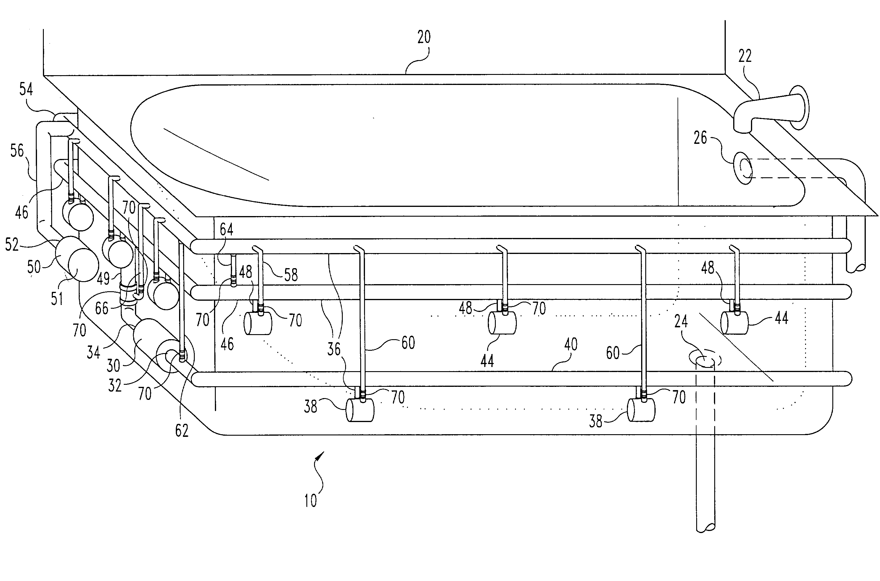
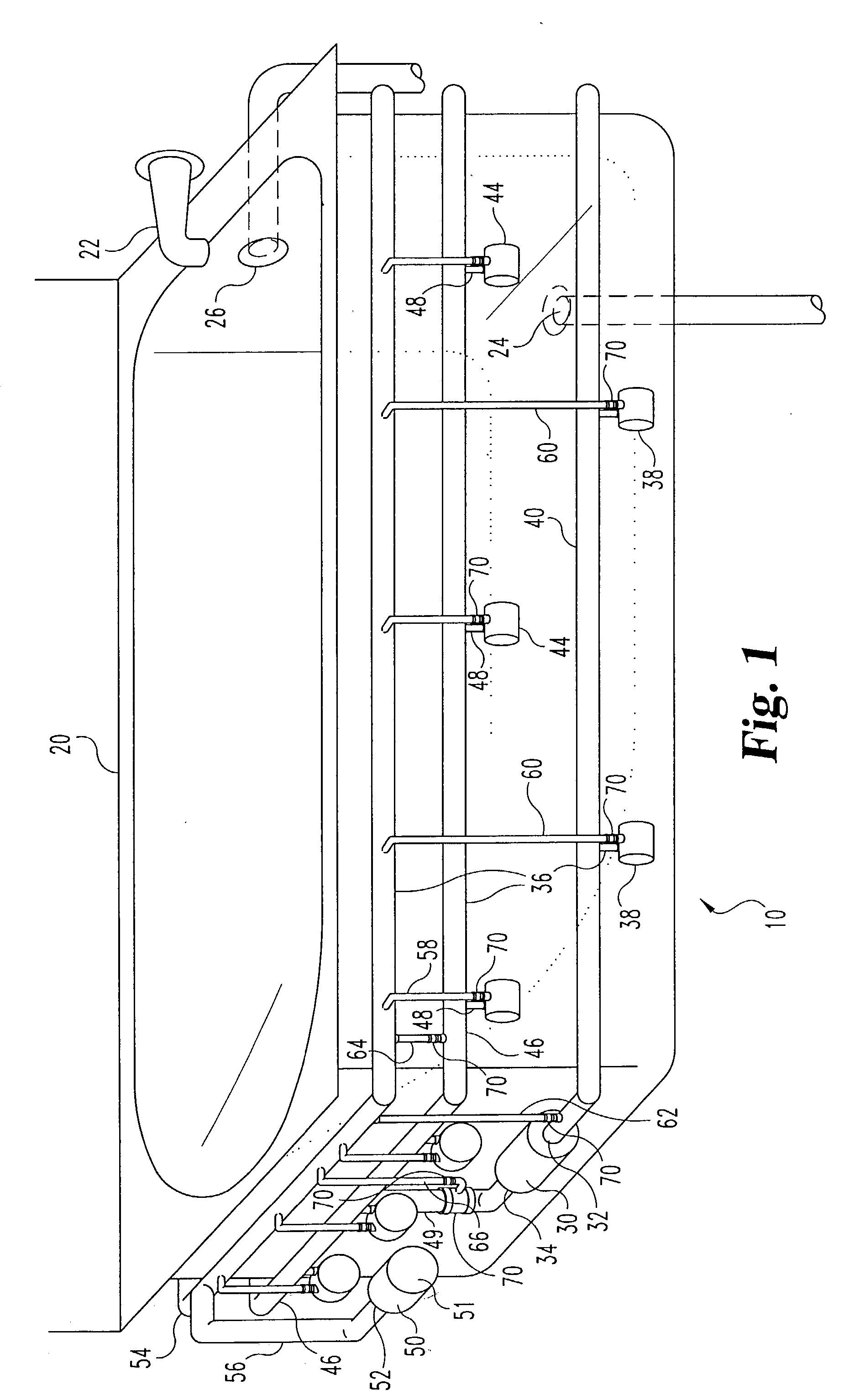
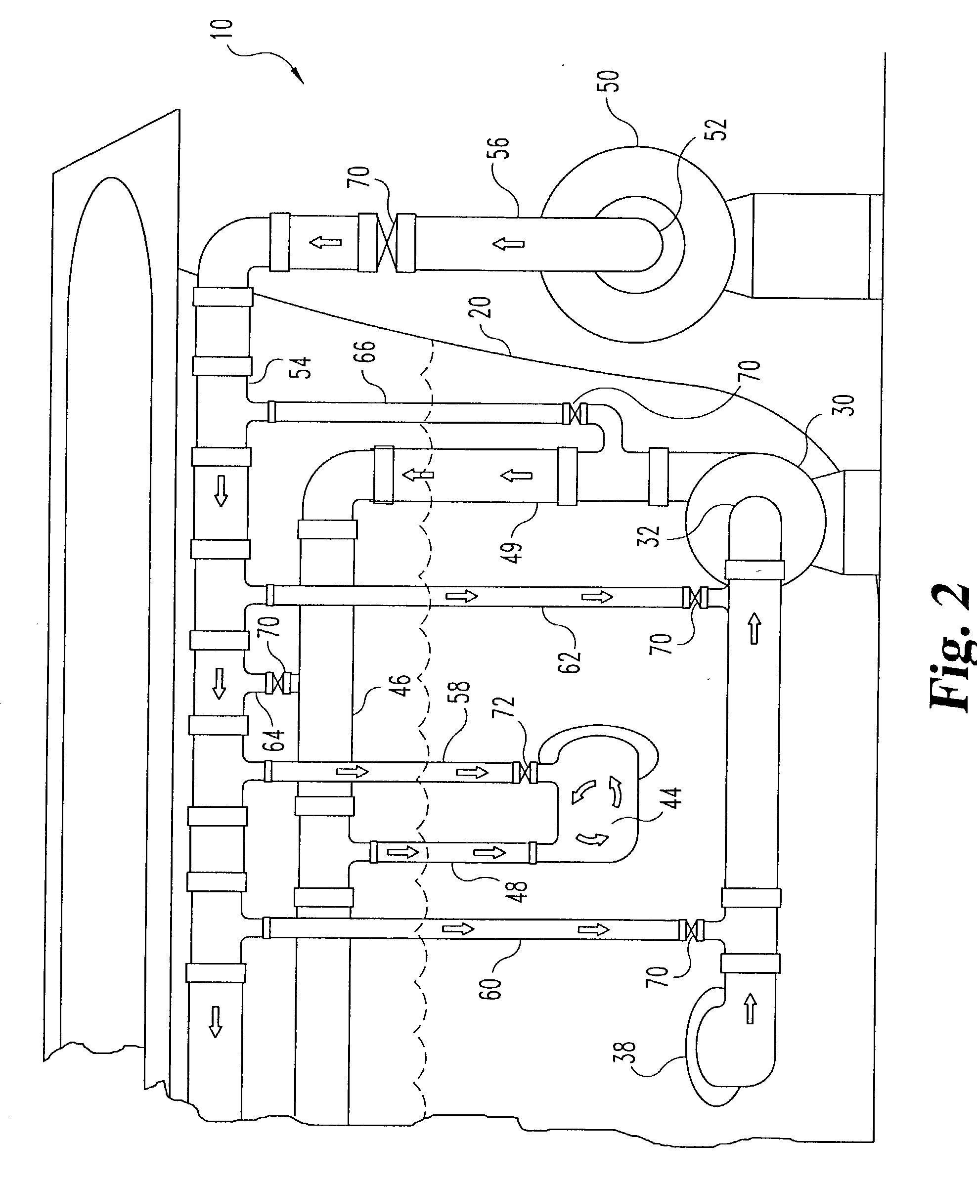
[0032]FIGS. 1 and 2 illustrate one embodiment of the present invention, a system 10 for purging residual water from the whirlpool plumbing of a whirlpool bathtub. The water purging system 10 is adapted to use air pressure to blow residual or standing water from the water circulation plumbing used to generate the “whirlpool” effect in a whirlpool bathtub 20. The whirlpool bathtub 20 typically includes a water inlet 22 a...


PUM


Abstract

The present invention relates to a system for automatically purging residual water from the whirlpool plumbing of a whirlpool bath. The system includes a bathtub, a primary water inlet in hydraulic communication with the bathtub, a primary water outlet in hydraulic communication with the bathtub, a plunger actuatable to engage the primary water outlet to prevent water flow through the primary water outlet, an auxiliary water outlet in hydraulic communication with the bathtub and positioned to define a maximum water level, a hydraulic pump having a water outlet port and a water inlet port, an air pump having an air inlet port and an air outlet port, at least one suction fitting formed in the bathtub, at least one hydraulic suction conduit extending between the at least one suction fitting to the water inlet port and connecting the at least one suction fitting in hydraulic communication to the water inlet port, at least one jet nozzle formed in the bathtub, a water manifold substantially positioned above the maximum water level, a water manifold conduit extending between the water outlet port and the water manifold and connecting the water outlet port to the water manifold in hydraulic communication therewith, at least one water delivery conduit extending between the water manifold and the at least one jet nozzle and connecting the water manifold to the at least one jet nozzle in hydraulic communication therewith, an air manifold positioned above the water manifold, an air pump delivery conduit extending between the air pump outlet and the air manifold and connecting the air pump outlet in pneumatic communication with the air manifold, and at least one air nozzle conduit extending between the air manifold and the at least one jet nozzle and connecting the air manifold in pneumatic communication to the at least one jet nozzle, at least one air suction conduit extending between the air manifold and the at least one suction fitting and connecting the air manifold in pneumatic communication to the at least one suction fitting. When the bathtub is filled with water the plunger is automatically disengaged for a predetermined length of time to flush the water manifold, the water manifold conduit, the at least one water delivery conduit and the at least one jet nozzle. Also, when the bathtub is substantially drained, the air pump may be actuated to introduce air into the at least one jet nozzle, the at least one suction fitting, the water manifold, the at least one water delivery conduit, and the at least one hydraulic suction conduit to purge residual water therefrom.

Description

CROSS-REFERENCE TO RELATED APPLICATIONS [0001] This application claims priority to U.S. patent application Ser. No. 09 / 849,659, filed May 4, 2001, which is a continuation-in-part U.S. patent application Ser. No. 09 / 544,157, filed Apr. 6, 2000.TECHNICAL FIELD OF THE INVENTION [0002] The present invention relates generally to plumbing fixtures, and, more particularly, to a method and apparatus for automatically disinfecting water in the water lines, fixtures, and jet manifolds during filling and / or draining of the bathtubs, spa vessels, toilets, and / or urinals. BACKGROUND OF THE INVENTION [0003] A whirlpool bath or spa typically includes a tub in which the water is circulated around the bather to provide a relaxing and therapeutic environment. Whirlpool baths generally accomplish this through the use of a hydraulic pump to circulate water from the interior of the bathtub through plumbing located on the exterior of the bathtub and back into the tub through a plurality of nozzles. Whirl...

Claims


Application Information

Patent Timeline
IPC IPC(8): A47K3/10A47K3/00A61H33/00A61H33/02A61H33/14
CPCA47K3/10A61H33/0087A61H33/02A61H33/6068A61H2033/023A61H33/60A61H33/6073A61H2033/002
Inventor GLOODT, CARY
Owner CEG HLDG
Features
  • Generate Ideas
  • Intellectual Property
  • Life Sciences
  • Materials
  • Tech Scout
  • Unparalleled Data Quality
  • Higher Quality Content
  • 60% Fewer Hallucinations
Learn More