
Exhaust emission purification apparatus of compression ignition type internal combustion engine

a technology of exhaust gas purification and compression ignition, which is applied in the direction of mechanical equipment, machines/engines, and non-fuel substance addition to fuel, etc., can solve the problems of large amount of soot produced, nosub>x /sub>storing catalyst cannot be made to release nosub>x /sub>well, and oxygen in the exhaust gas is rapidly consumed

Inactive Publication Date: 2006-03-16
TOYOTA JIDOSHA KK
View PDF2 Cites 49 Cited by
  • Summary
  • Abstract
  • Description
  • Claims
  • Application Information

AI Technical Summary

Benefits of technology

[0010] To achieve the above object, according to the present invention, provision is made of fuel adding means for adding particulate fuel into exhaust gas, an HC adsorbing and oxidation catalyst arranged in an engine exhaust passage downstream of the fuel adding means for adsorbing and oxidizing hydrocarbons contained in the exhaust gas, and an NOx storing catalyst arranged in the engine exhaust passage downstream of the HC adsorbing and oxidation catalyst for storing NOx contained in the exhaust gas when the air-fuel ratio of the inflowing exhaust gas is lean and releasing the stored NOx when the air-fuel ratio of the inflowing exhaust gas becomes the stoichiometric air-fuel ratio or rich, particulate fuel is added from the fuel adding means when making the air-fuel ratio of the exhaust gas flowing into the NOx storing catalyst rich to make the NOx storing catalyst release NOx, the amount of addition of particulate fuel at this time is set to an amount whereby the air-fuel ratio of the exhaust gas flowing into the HC absorbing and oxidation catalyst becomes a rich air-fuel ratio smaller than the rich air-fuel ratio when flowing into the NOx storing catalyst, and after the added particulate fuel is adsorbed at the HC adsorbing and oxidation catalyst, the majority of the adsorbed fuel is oxidized in the HC adsorbing and oxidation catalyst and the air-fuel ratio of the exhaust gas flowing into the NOx storing catalyst is made rich over a longer period than when the air-fuel ratio of the exhaust gas flowing into the HC adsorbing and oxidation catalyst is made rich.

Problems solved by technology

However, when using such an NOx storing catalyst, it is necessary to make the NOx storing catalyst release the NOx before the NOx storing capability of the NOx storing catalyst becomes saturated.
However, if making the air-fuel mixture in the combustion chamber rich, there is the problem that a large amount of soot is produced.
However, when injecting fuel into the engine exhaust passage upstream of the NOx storing catalyst, there is the problem that the injected fuel is not sufficiently gasified and therefore the NOx storing catalyst cannot be made to release NOx well.
However, in this internal combustion engine, when the temperature of the HC adsorbing catalyst becomes near the activation temperature, that is, near 200° C., the oxidation reaction of the adsorbed HC becomes active and as a result the oxygen in the exhaust gas is rapidly consumed, so the oxygen concentration in the exhaust gas rapidly falls.
Therefore, the above problem arises.
Further, in this internal combustion engine, the period when the temperature of the HC adsorbing catalyst becomes near the activation temperature, that is, the period when a sufficient amount of oxygen is consumed in the HC adsorbing catalyst, is limited, so the temperature of the HC adsorbing catalyst will not become the activation temperature in the period required as seen from the action of the NOx storing catalyst releasing the NOx and consequently there is the problem that the NOx storing catalyst cannot release NOx when the NOx storing catalyst has to release the NOx.

Method used


Image

  • Exhaust emission purification apparatus of compression ignition type internal combustion engine
  • Exhaust emission purification apparatus of compression ignition type internal combustion engine
  • Exhaust emission purification apparatus of compression ignition type internal combustion engine

Examples


Embodiment Construction

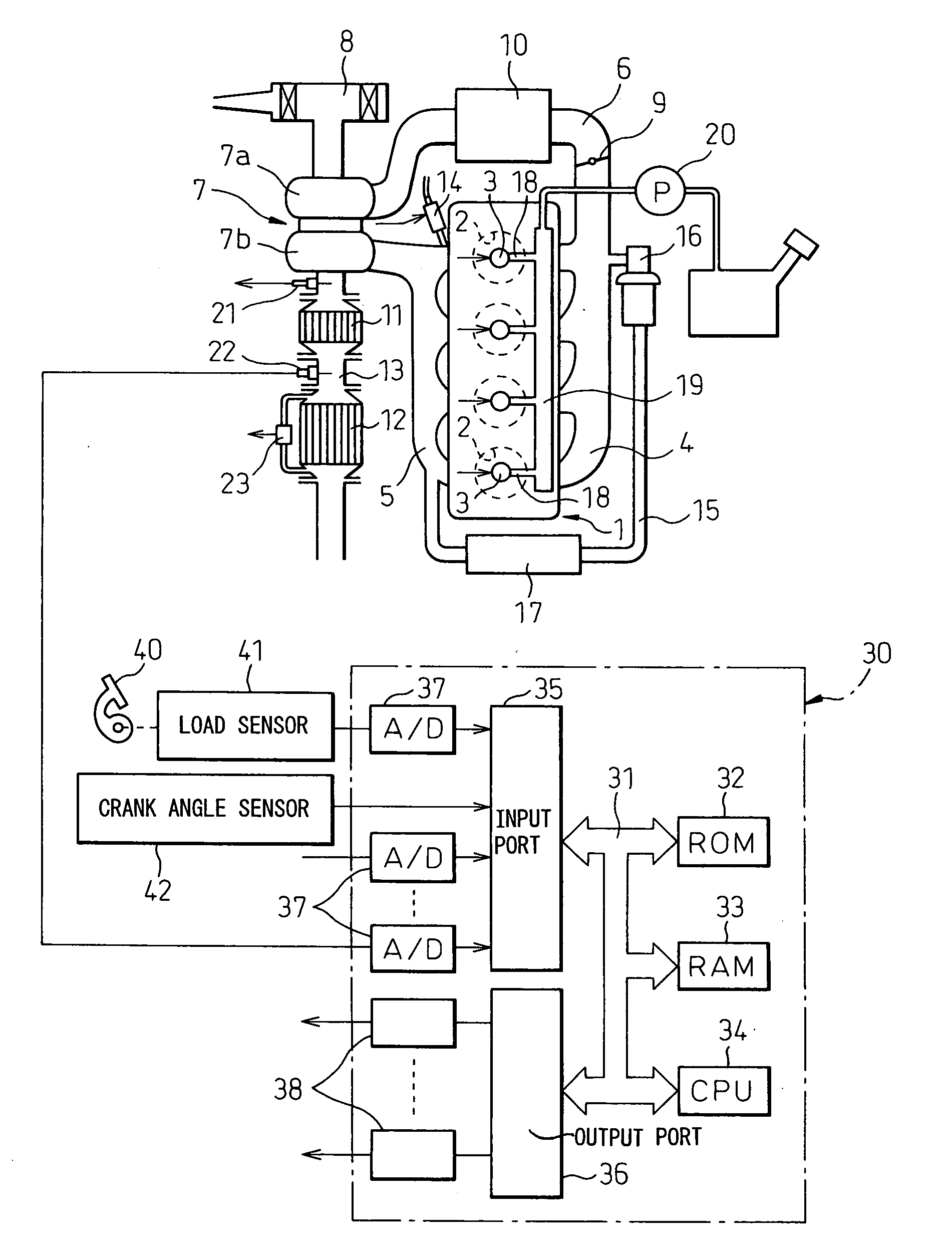
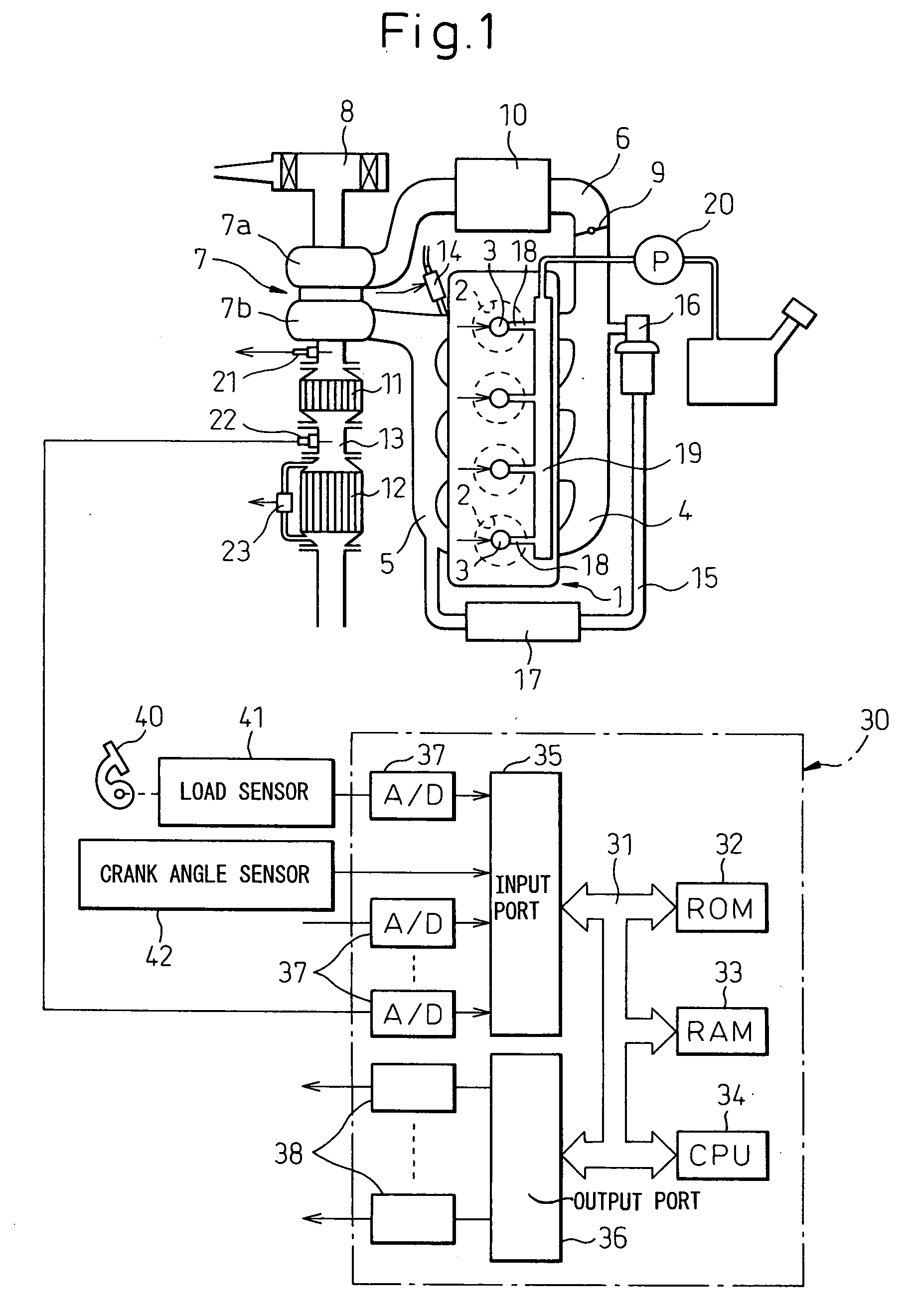
[0028]FIG. 1 shows an overview of a compression ignition type internal combustion engine.

[0029] Referring to FIG. 1, 1 indicates an engine body, 2 a combustion chamber of each cylinder, 3 an electronically controlled fuel injector for injecting fuel into each combustion chamber 2, 4 an intake manifold, and 5 an exhaust manifold. The intake manifold 4 is connected through an intake duct 6 to an outlet of a compressor 7a of an exhaust turbocharger 7. The inlet of the compressor 7a is connected to an air cleaner 8. Inside the intake duct 6 is arranged a throttle valve 9 driven by a step motor. Further, around the intake duct 6 is arranged a cooling device 10 for cooling the intake air flowing through the inside of the intake duct 6. In the embodiment shown in FIG. 1, the engine cooling water is guided into the cooling device 10. The engine cooling water cools the intake air. On the other hand, the exhaust manifold 5 is connected to an inlet of an exhaust turbine 7b of the exhaust turb...


PUM


Abstract

A fuel adding valve (14), an HC adsorbing and oxidation catalyst (11), and a NOx storing catalyst (12) are successively arranged in an exhaust passage of an internal combustion engine toward the downstream side. When the NOx storing catalyst (12) should release NOx, particulate fuel is added from the fuel adding valve (14). This fuel is adsorbed once at the HC adsorbing and oxidation catalyst (11), then gradually evaporates to make the air-fuel ratio of the exhaust gas flowing into the NOx storing catalyst (12) rich. Due to this, NOx is released from the NOx storing catalyst (12).

Description

TECHNICAL FIELD [0001] The present invention relates to an exhaust purification device of a compression ignition type internal combustion engine. BACKGROUND ART [0002] Known in the art is an internal combustion engine having arranged in an engine exhaust passage an NOx storing catalyst which stores NOx contained in exhaust gas when the air-fuel ratio of the inflowing exhaust gas is lean and releases the stored NOx when the oxygen concentration in the inflowing exhaust gas falls. In this internal combustion engine, the NOx produced when burning fuel under a lean air-fuel ratio is stored in the NOx storing catalyst. [0003] However, when using such an NOx storing catalyst, it is necessary to make the NOx storing catalyst release the NOx before the NOx storing capability of the NOx storing catalyst becomes saturated. In this case, if making the air-fuel ratio of the exhaust gas flowing into the NOx storing catalyst rich, it is possible to make the NOx storing catalyst release the NOx an...

Claims


Application Information

Patent Timeline
IPC IPC(8): F01N3/00F01N3/10F01N3/02F01N3/023F01N3/025F01N3/029F01N3/08F01N3/20F01N3/36F01N13/02F02B37/00F02M25/07
CPCF01N3/0814F01N3/0835F01N3/0842F01N2610/03F01N13/009F02B37/00F02M25/0707F02M25/0731F02B29/0406F02M26/05F02M26/28F01N3/02F01N3/08F01N3/24F01N3/36
Inventor ASANUMA, TAKAMITSUHIROTA, SHINYAODA, TOMIHISA
Owner TOYOTA JIDOSHA KK
Features
  • Generate Ideas
  • Intellectual Property
  • Life Sciences
  • Materials
  • Tech Scout
  • Unparalleled Data Quality
  • Higher Quality Content
  • 60% Fewer Hallucinations
Learn More