Motorcycle exhaust system
a technology of exhaust system and motorcycle, which is applied in the direction of engine components, machines/engines, mechanical apparatus, etc., can solve the problems of unbalanced output between the engine cylinders, complication of the structure and increase of the cost, and insufficient purification function, etc., to achieve advantageous reduction of the number of catalytic converters, increase length, and simplify the effect of structur
- Summary
- Abstract
- Description
- Claims
- Application Information
AI Technical Summary
Benefits of technology
Problems solved by technology
Method used
Image

Examples
first embodiment
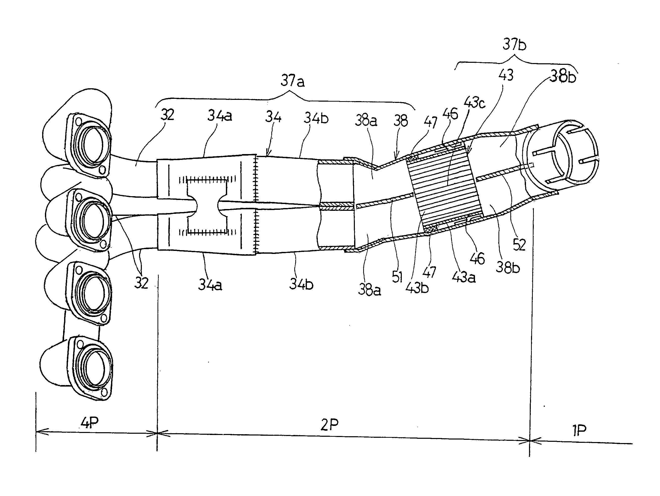
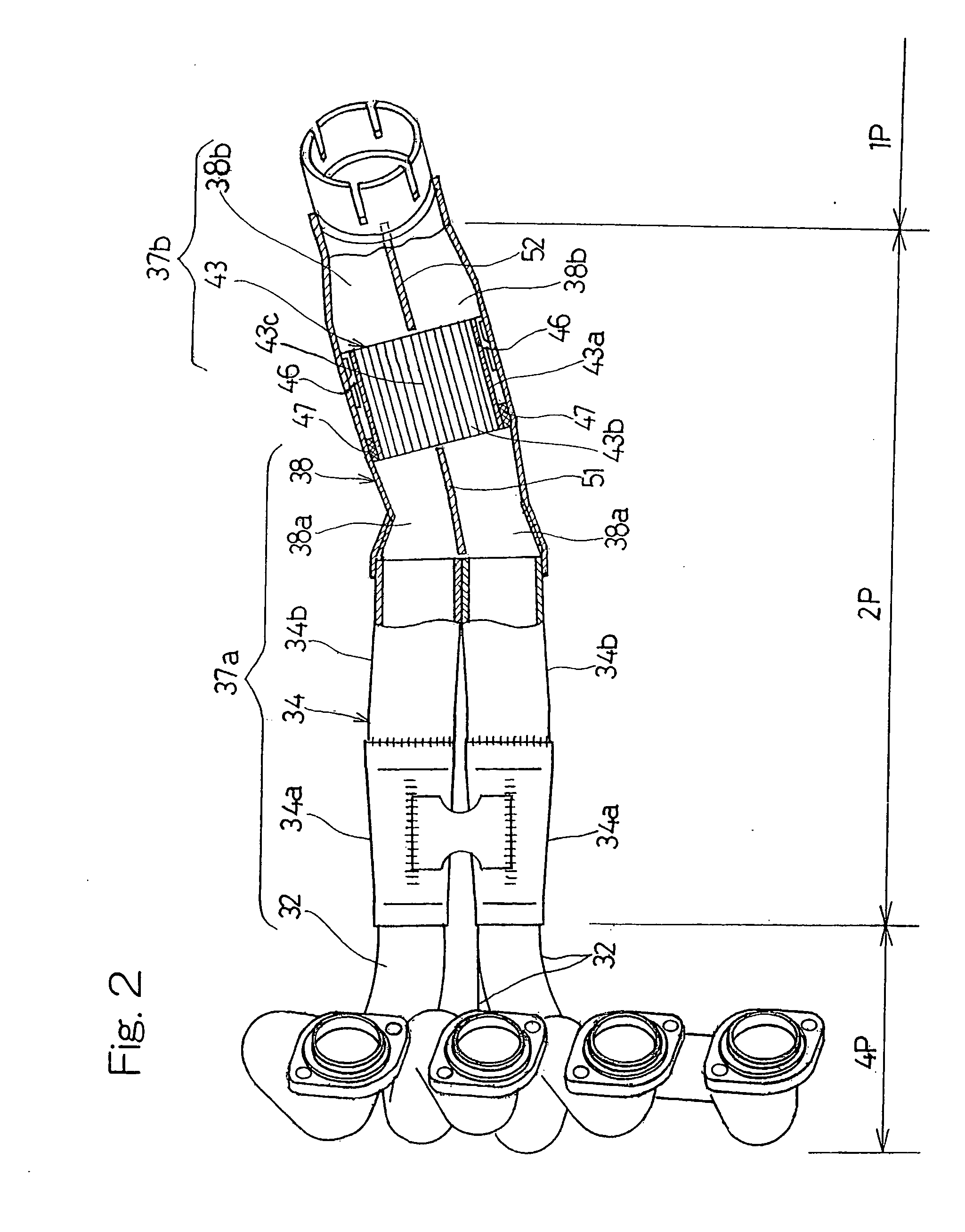
[0045] The relation between the number of revolutions of the combustion engine E and the engine output is illustrated in FIG. 4. In the chart shown in FIG. 4, comparison is made between the exhaust system A of the first embodiment in which the upstream partition plate 51 is set to have, for example, 80 mm in length and the downstream partition plate 52 is set to have, for example, 60 mm in length, both as measured along the longitudinal axis of the exhaust passage 37, are employed, and the exhaust system B in which neither the upstream partition plate 51 nor the downstream partition plate 52 is employed. The chart shown in FIG. 4 makes it clear that the use of the exhaust system A has resulted in increase of the engine output at the medium speed region. This is because the two flow paths region 2P of the exhaust passage 37 of the exhaust system B terminates at the downstream ends of the intermediate exhaust pipes 34 and is therefore shorter than that in the exhaust system A.
[0046] A...
third embodiment
[0050] The motorcycle exhaust system according to a third preferred embodiment of the present invention will now be described. Referring to FIGS. 6A and 6B, which illustrate a plan view and a fragmentary side sectional view, both on an enlarged scale, of an important portion of the exhaust system according to the present invention, respectively, the upstream partition plate, which has been shown by 51 as disposed upstream of the catalytic converter 43 in any one of the foregoing embodiments, is not employed and, instead, the intermediate exhaust pipes 34 are extended so as to have their downstream ends terminating in the vicinity of the upstream end of the catalytic converter 43 within the exhaust assemblage pipe 38. In this arrangement, a portion of the catalytic converter, which is adjacent a downstream end of a jointed wall 34c of the intermediate exhaust pipes 34, serves as a partition wall 43c.
[0051] Also, since each of the intermediate exhaust pipes 34 is made of a stainless ...
fourth embodiment
[0054] The relation between the number of revolutions of the combustion engine E, employing the exhaust system shown in FIG. 7, and the engine output is illustrated in FIG. 8. In the chart shown in FIG. 4, comparison is made between the exhaust system C, in which the two annular sealing members 47 and 47 are employed, and the exhaust system D in which none of the sealing members 47 and 47 is employed. The chart shown in FIG. 8 makes it clear that the exhaust system C has exhibited a higher increase of the engine output at the medium speed region than that exhibited by the exhaust system D.
PUM
 Abstract
Description
Claims
Application Information
 - R&D Engineer
- R&D Manager
- IP Professional
- Industry Leading Data Capabilities
- Powerful AI technology
- Patent DNA Extraction
Browse by: Latest US Patents, China's latest patents, Technical Efficacy Thesaurus, Application Domain, Technology Topic.
© 2024 PatSnap. All rights reserved.Legal|Privacy policy|Modern Slavery Act Transparency Statement|Sitemap