Submount for light emitting diode and its manufacturing method

Active Publication Date: 2006-03-16
HITACHI KYOWA ENG +1
View PDF4 Cites 39 Cited by
  • Summary
  • Abstract
  • Description
  • Claims
  • Application Information

AI Technical Summary

Benefits of technology

[0013] With that method, the submount for the light emitting diode can be obtained which includes the reflector and has a compact size.
[0014] Thus, according to the present invention, it is

Problems solved by technology

With the related art that the reflector is made of another material (a metal or a plastic or the like onto which a metal thin film is affixed) and a submount with an LED mounted thereon is disposed in the reflector, however, a problem arises in

Method used


Image

  • Submount for light emitting diode and its manufacturing method
  • Submount for light emitting diode and its manufacturing method
  • Submount for light emitting diode and its manufacturing method

Examples


Embodiment Construction

[0022] A submount for a light emitting diode (LED) and its manufacturing method according to a first embodiment of the present invention will be described below with reference to FIGS. 1-7.

[0023] First, a description is made of the entire structure of the submount for the LED according to this embodiment with reference to FIGS. 1 and 2.

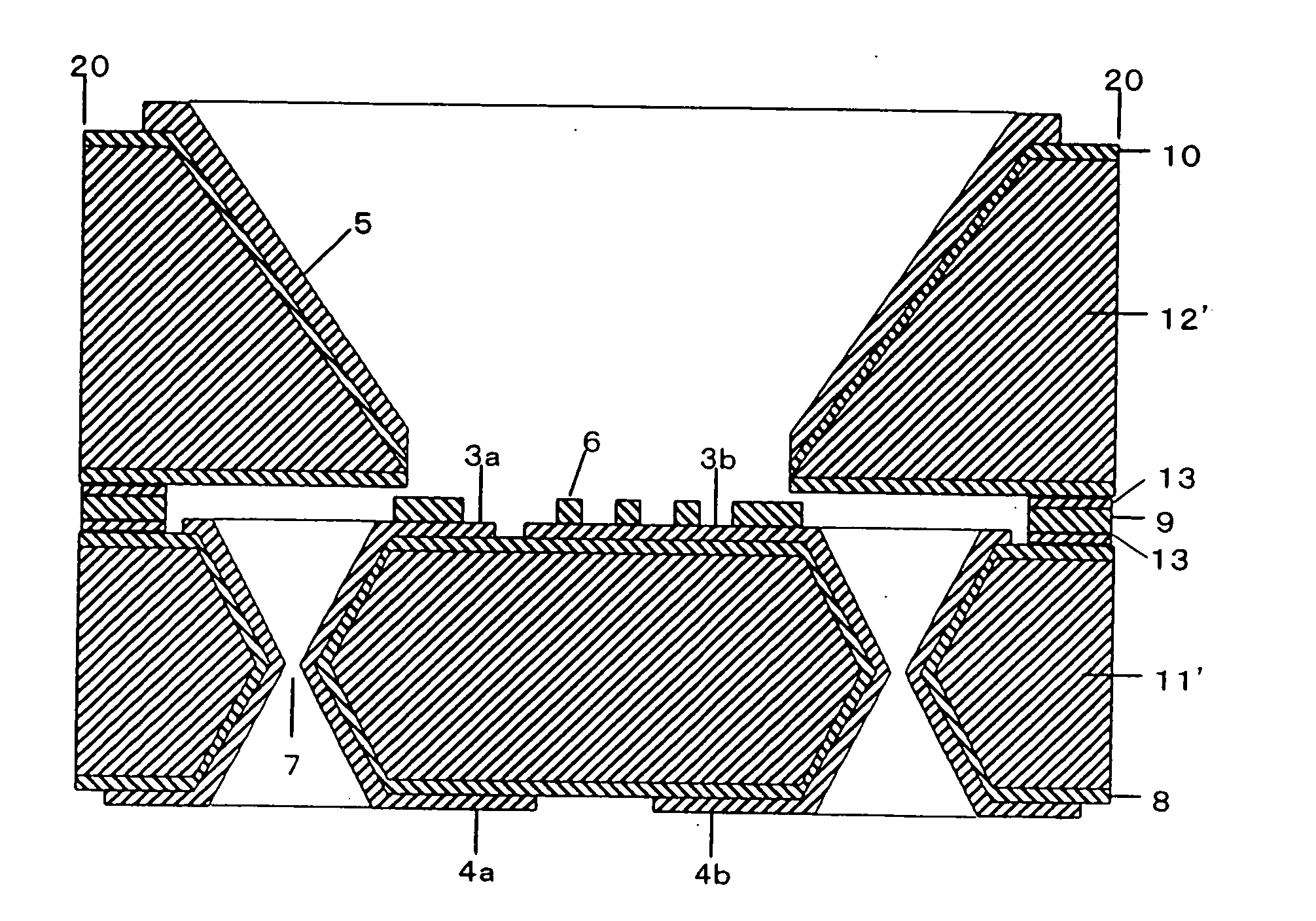
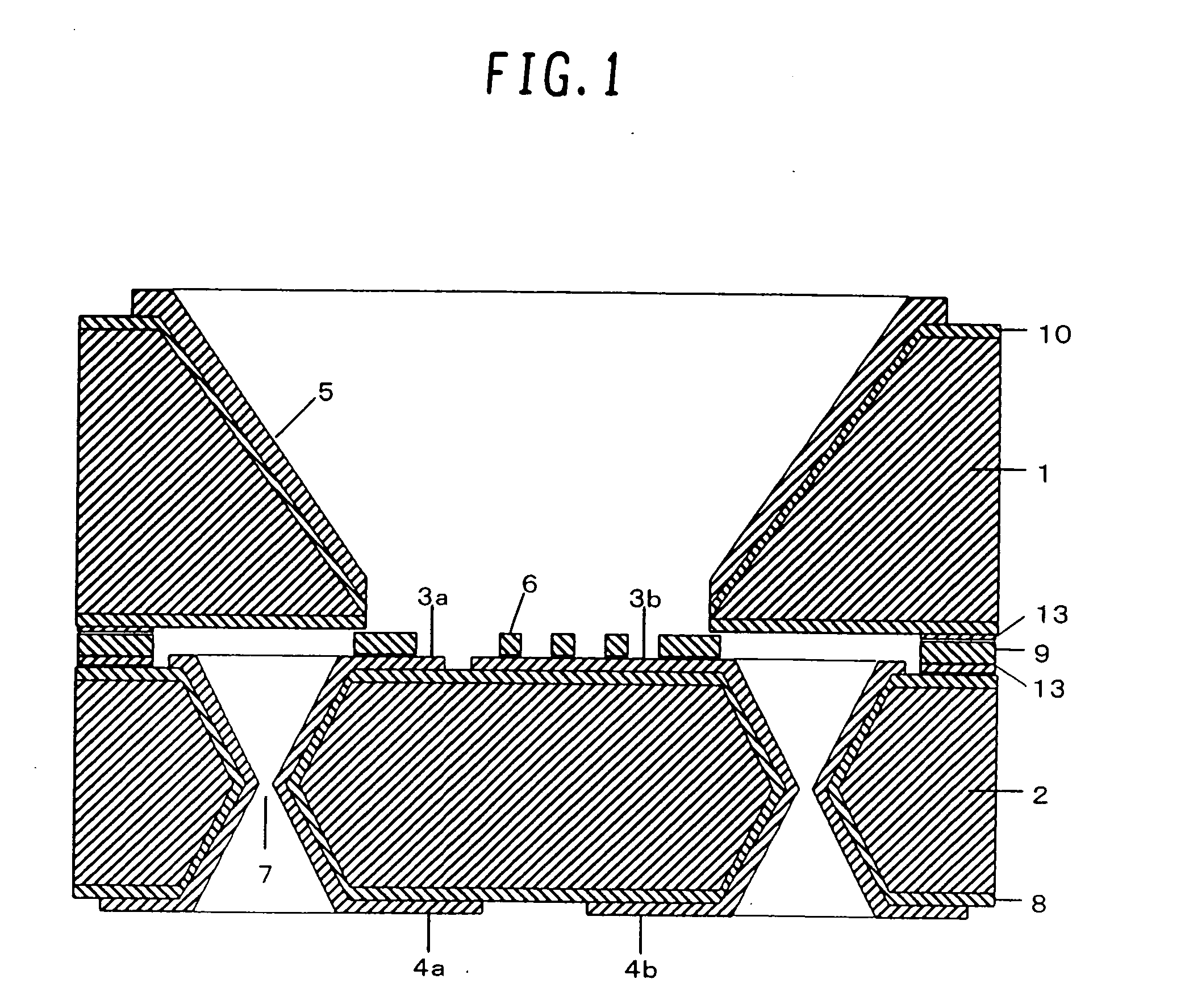
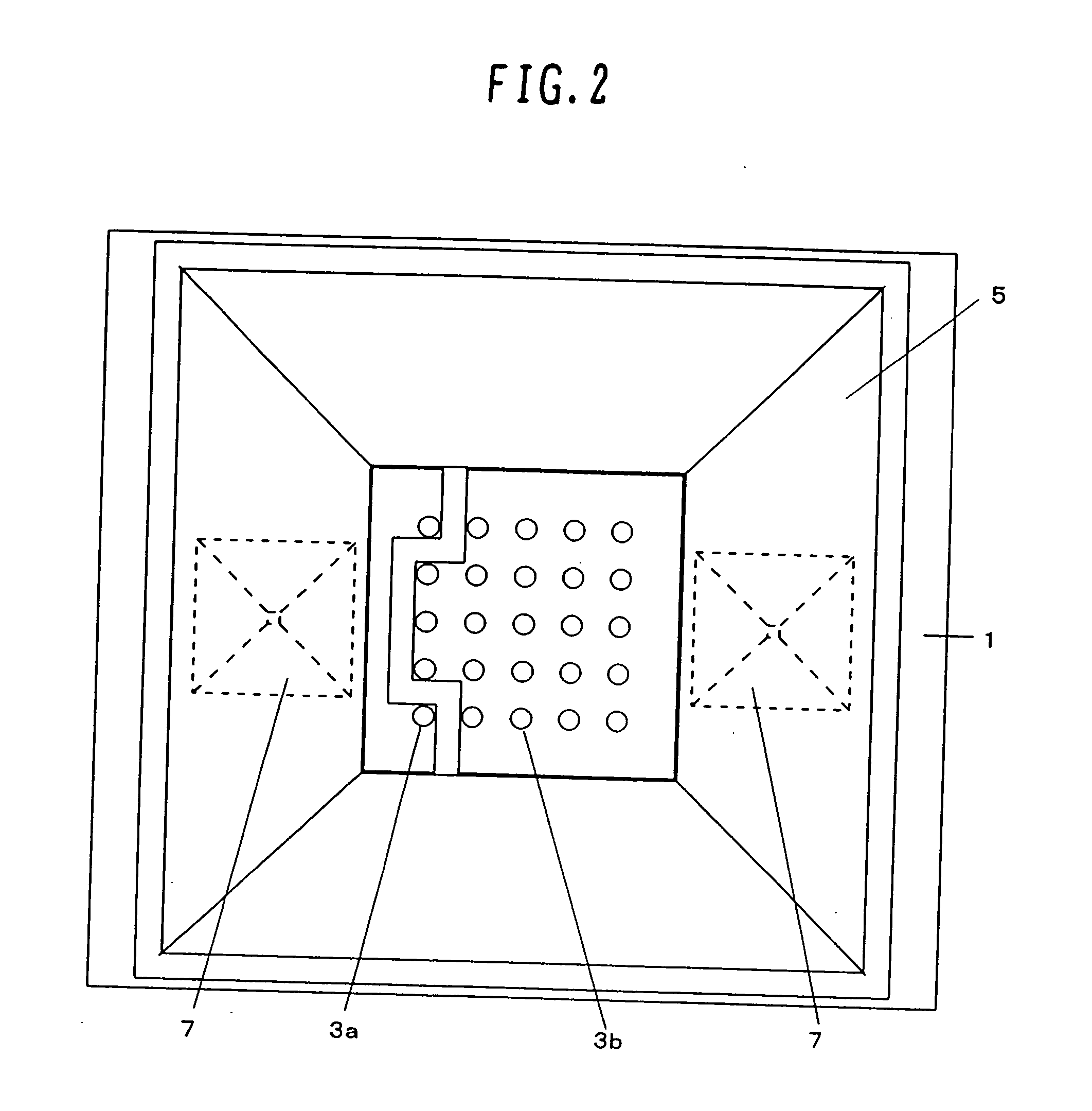
[0024]FIG. 1 is a sectional view showing the entire structure of the submount for the LED according to one embodiment of the present invention, and FIG. 2 is a plan view showing the entire structure of the submount for the LED according to one embodiment of the present invention. Note that, in FIGS. 1 and 2, the same symbols denote the same components.

[0025] As shown in FIG. 1, the submount for the LED according to this embodiment is of a structure that a silicon (Si) reflector 1 is joined onto a silicon (Si) base substrate 2 by a thin film solder 9. The Si base substrate 2 is formed by wet etching that is performed from both the front side and the...


PUM


Abstract

A submount for a light emitting diode and its manufacturing method, the submount including a reflector and having a compact size. The submount for the light emitting diode comprises a Si base substrate having input/output terminals formed on a front side thereof, and a Si reflector having a sloped through hole and a reflecting film formed at least on a slope defining the through hole. The Si reflector is mounted on the Si base substrate and is fixedly joined to the Si base substrate. The Si reflector and the Si base substrate are joined to each other by a thin film solder.

Description

BACKGROUND OF THE INVENTION [0001] 1. Field of the Invention [0002] The present invention relates to a submount for a light emitting diode and its manufacturing method. [0003] 2. Description of the Related Art [0004] As a package for mounting an optical part, JP-A-11-265957 (Patent Document 1) discloses one example in which a frame is prepared by forming a cavity in one green-sheet with punching, and a bottom plate is prepared, for example, by forming through holes in another green-sheet and metalizing certain regions thereof. Then, the frame and the bottom are laminated together and are subjected to heat pressing and sintering under a reduction atmosphere, following by dicing the laminate into a predetermined size. Also, JP-A-2000-138305 (Patent Document 2) discloses another example in which a frame made of epoxy resins is formed by injection molding or transfer molding, and the frame is joined to a ceramic base substrate by an epoxy-resin adhesive. A high-brightness LED lamp requi...

Claims


Application Information

Patent Timeline
IPC IPC(8): H01L33/00H01L31/072H01L33/46H01L33/48H01L33/60H01L33/62H01L33/64
CPCH01L33/486H01L33/50H01L33/60H01L33/62H01L2924/12041H01L2224/16H01L2924/01079H01L2924/01019H01L33/641
Inventor TAKEMORI, HIDEAKIHIGASHIYAMA, SATOSHIMORI, KENJITOHMON, RYOICHIHIROSE, MINORUKAWAGUCHI, HIROAKI
Owner HITACHI KYOWA ENG
Why Eureka
Try Eureka