
Chucking and focusing device for a telescope eyepiece and its production process

a technology of focusing device and telescope, which is applied in the direction of telescopes, mountings, instruments, etc., can solve the problems of difficult to achieve good focusing image quality, complicated structure of conventional telescopes, and difficulty in focusing good image quality, so as to simplify the focusing structure and production process, and minimize the eccentricity of axes

Inactive Publication Date: 2006-03-16
SUN LONG OPTICS
View PDF9 Cites 7 Cited by
  • Summary
  • Abstract
  • Description
  • Claims
  • Application Information

AI Technical Summary

Benefits of technology

[0009] This invention has been devised to offer a chucking and focusing a telescope eyepiece to simplify its focusing structure and production process, and mainly to minimize eccentricity of axes between an eyepiece and an eyepiece barrel.
[0011] A first feature of the invention is a chuck provided with male threads on an end connected with an eyepiece, and multiple elastic strips formed on the outer end section with their ends expanding outward a little. Further a constrict ring is provided with female threads to engage the eyepiece barrel and an annular projecting ridge in an inner surface and located outside the elastic strips. Then the eyepiece is inserted in a space defined by the elastic strips. Rotating the constrict ring can force the projecting ridge move toward the end of the elastic strips so that the elastic strips may clamp the eyepiece tightly, with the axis of the eyepiece not biasing from the axis of the eyepiece barrel after adjustment.

Problems solved by technology

However, the conventional telescope has following disadvantages in usage.
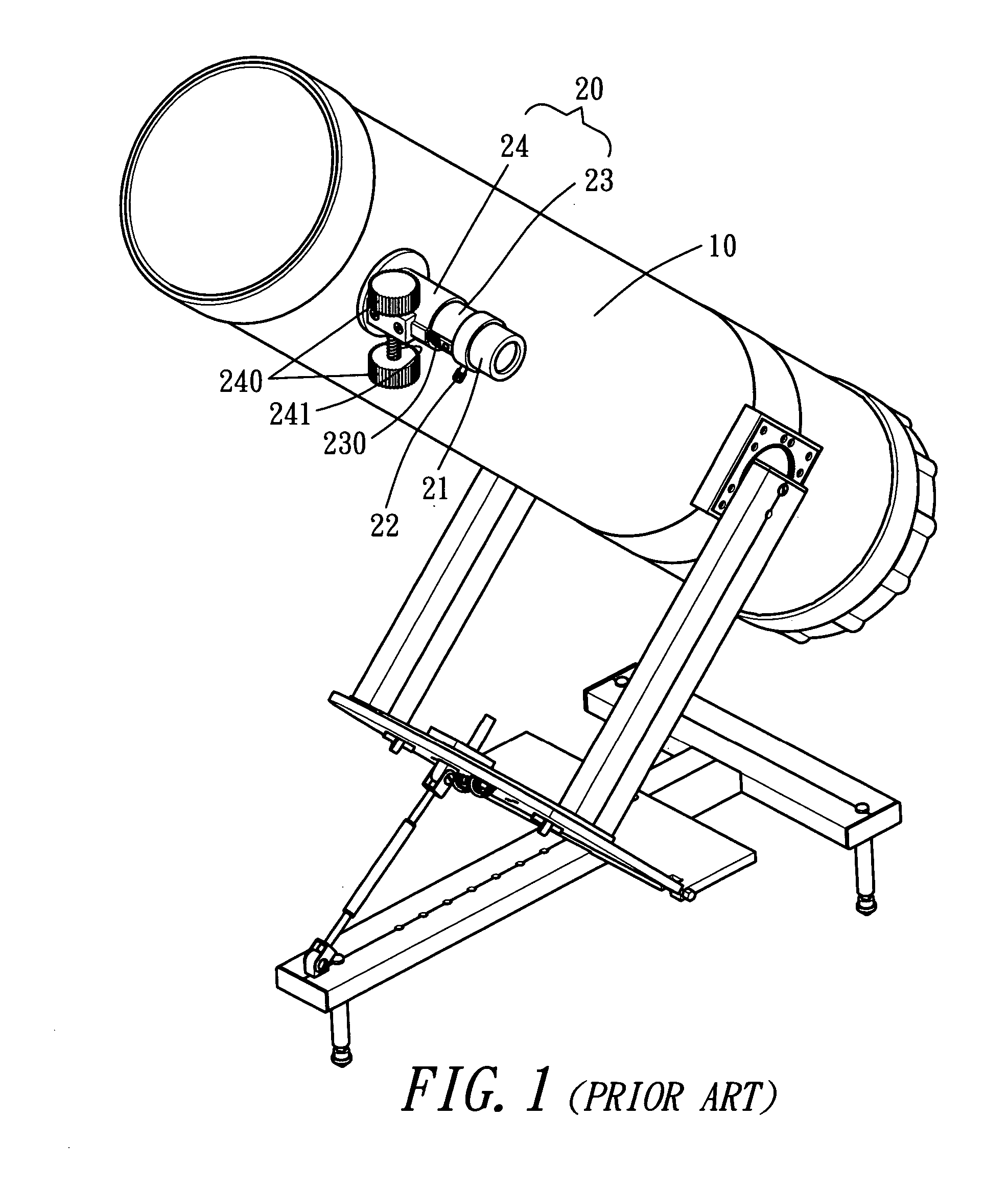
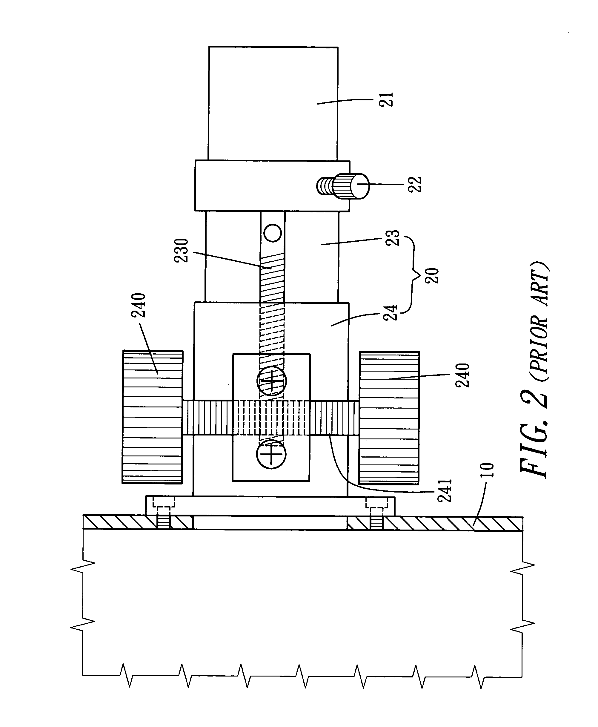
This way of fastening obviously push eyepiece 21's optical axis away from the axis of the eyepiece barrel causing eccentricity between two axes, and thus causing difficulty of focusing good image quality.
When the inner tube 23 and the outer tube 24 are adjusted in their length, it has to depend on matching movement of the two adjust wheels 240, the worm 241 and the rack 230, complicated in its structure, and subsequent high cost, and rather slow in its adjusting speed.

Method used


Image

  • Chucking and focusing device for a telescope eyepiece and its production process
  • Chucking and focusing device for a telescope eyepiece and its production process
  • Chucking and focusing device for a telescope eyepiece and its production process

Examples


Embodiment Construction

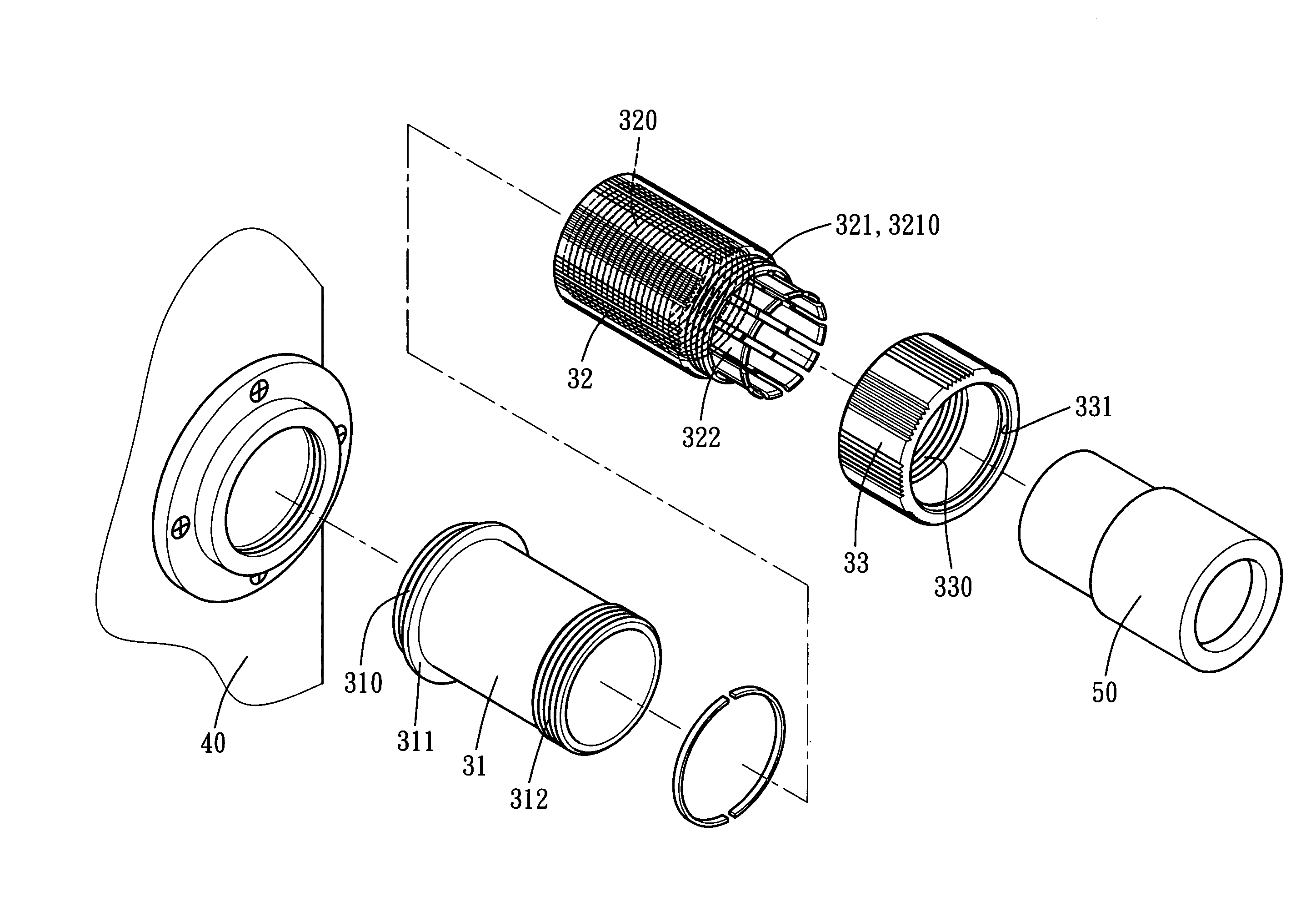
[0022] A preferred embodiment of a chuck for focusing a telescope eyepiece in this invention as shown in FIGS. 3, and 4, includes a eyepiece barrel 30 consisting of an inner tube 31 and an outer tube and damper (or chuck) 32 combined together.

[0023] The inner tube 31, referring to FIGS. 4 and 5, is provided with first male threads 310 at one end, a stop flange 311 just behind the male threads 310, and second male threads 312 at the other end. The male threads 310 engage a cylindrical body 40 of a telescope, and the stop flange 311 is to be stopped by an outer wall of the cylindrical body 40.

[0024] The outer tube and damper 32 is provided with female threads 320 to engage the male threads 310 of the inner tube 31, a neck 321 on the end connected with an eyepiece 50 and having a reverse male threads 3210 and an elastic strips 322 radially arranged to extend from the neck 321 and expanding outward a little.

[0025] A constrict ring 33 is further provided, having reverse female threads...


PUM


Abstract

A chucking and focusing device for an telescope eyepiece includes an eyepiece barrel consisting of an inner tube and an outer tube and damper formed with multiple elastic strips in a radial shape, and a constrict ring with female threads engaging the male threads of the outer tube and clamper. The inner tube, the outer tube and damper and the constrict ring are threadably combined with one another, so that rotating the constrict ring can gradually clamp the elastic strip and then the eyepiece tightly with its axis not biasing. A production process for the chucking and focusing device for an telescope eyepiece includes two steps. One step is to machine multiple lengthwise grooves in an inner surface of a metal constrict tube with its thickness being the same as the depth of the elastic strip. Another step is to machine the metal constrict tube to form elastic strips until the grooves are exposed, forming a single elastic strip between every two grooves, finishing forming of the clamper.

Description

REFERENCE TO RELATED APPLICATION [0001] The present application claims the priority of provisional patent application Ser. No. 60 / 642,343 of inventor Chun-Chang Kuo (a.k.a. Paul Kuo) titled “Chucking and Focusing Device For a Telescope Eyepiece and its Production Process” filed Jan. 6, 2005 in the United States Patent and Trademark Office.BACKGROUND OF THE INVENTION [0002] 1. Field of the Invention [0003] This invention relates to a chucking and focusing device for a telescope eyepiece and its production process, particularly to one possible to clamp and focus an eyepiece without significant eccentricity, and a method for producing it. [0004] 2. Description of the Prior Art [0005] A conventional Newtonian reflective telescope shown in FIGS. 1 and 2, includes a tubing body 10, an eyepiece barrel 220 fixed vertically on one side of the barrel body 10 and having one end fitting around an eyepiece 21, and then the eyepiece 21 and the eyepiece barrel 20 are tightly combined together with...

Claims


Application Information

Patent Timeline
Patent Type & Authority Applications(United States)
IPC IPC(8): G02B7/02
CPCG02B7/04G02B25/001G02B23/16
Inventor KUO, PAUL
Owner SUN LONG OPTICS
Learn More