Reinforced beam system

一种加强梁、加强元件的技术,应用在模块化加强梁连接件系统领域,能够解决部件大、成本高等问题,达到优化抗弯强度和抗剪强度、减少侧向不稳定性的效果

Inactive Publication Date: 2020-01-07
拉姆纳冯
View PDF3 Cites 0 Cited by
  • Summary
  • Abstract
  • Description
  • Claims
  • Application Information

AI Technical Summary

Problems solved by technology

As a result, stress concentrates on the flange, making the part larger and more expensive

Method used


Image

  • Reinforced beam system
  • Reinforced beam system
  • Reinforced beam system

Examples


Embodiment Construction

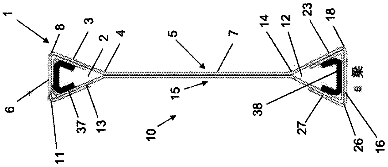
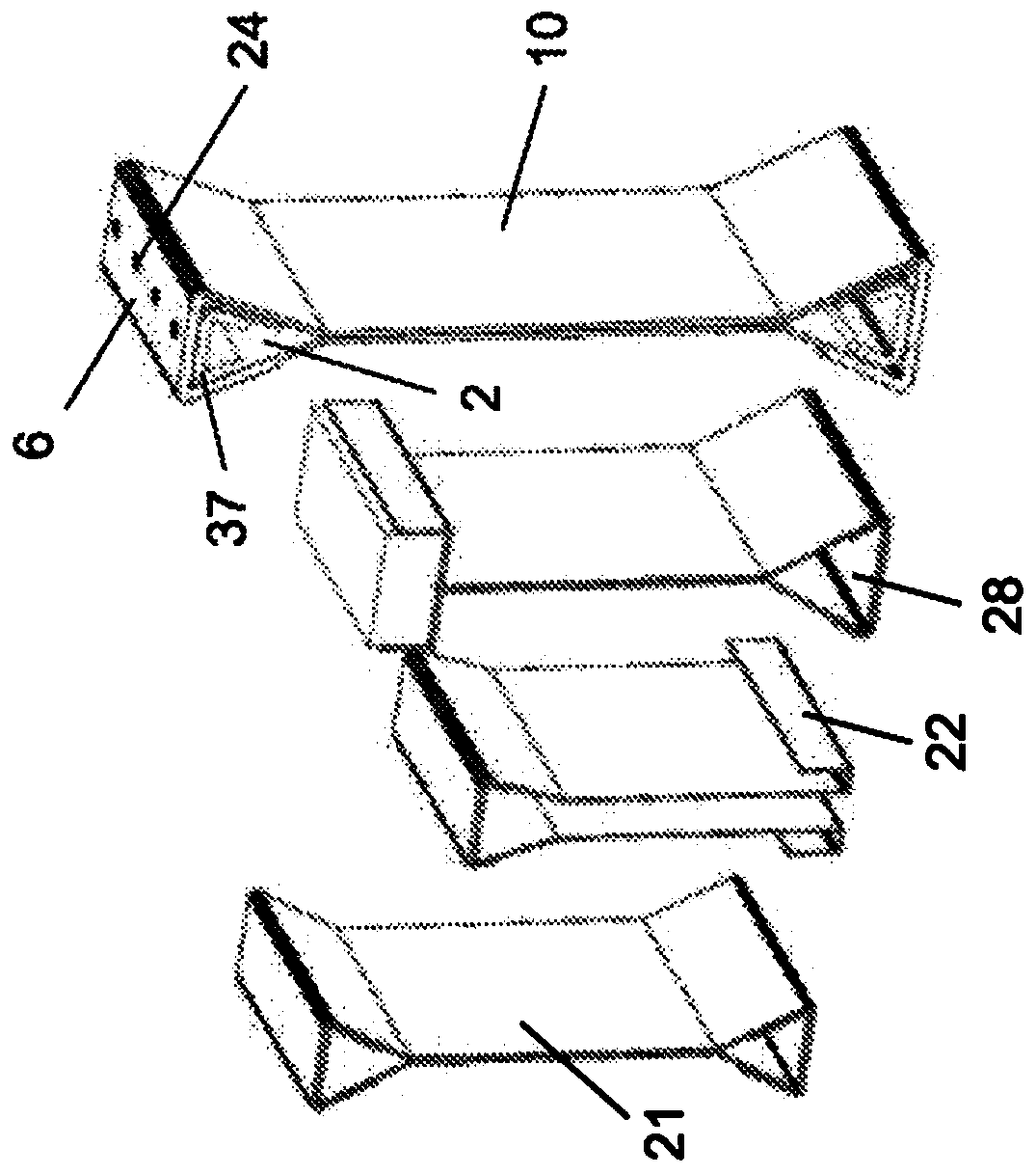
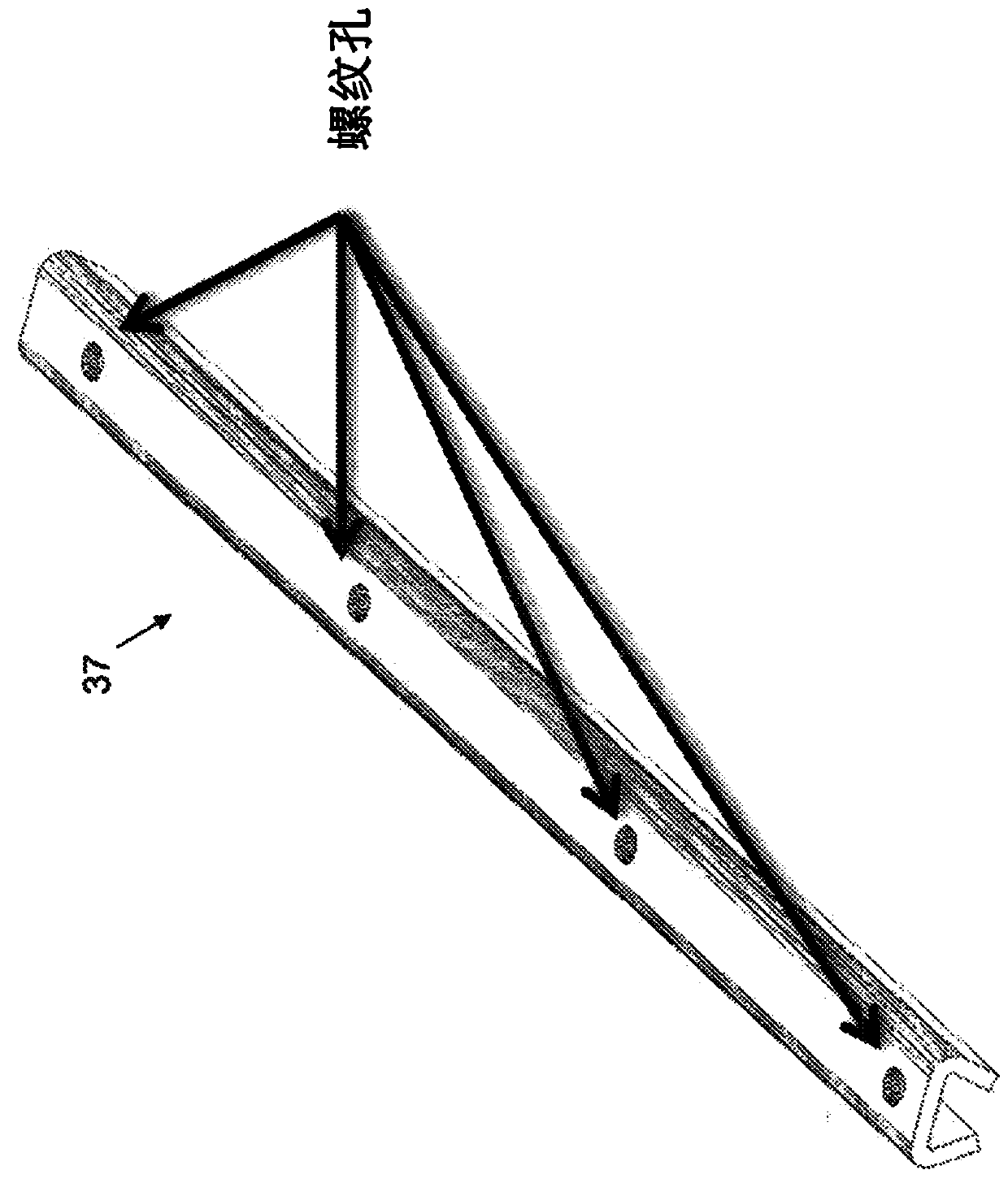
[0068] The present invention is a novel stiffening beam system comprising one or more lightweight structural beams having two triangular shaped head sections which provide increased lateral stability and strength-to-weight ratio, and at least one reinforcing element inserted inside and connected to the head portion of the beam.

[0069] Although some prior art beams have been constructed with triangular shaped head sections made by the cold rolling process, these head sections are closed triangles and their third side cannot be formed quickly and automatically due to the The inaccessibility of three sides and the inability of the roller to support the fed sheet metal because it bends to form a closed triangle. In contrast, the beam of the present invention is a composite beam made of two separate and oppositely oriented members arranged such that the corresponding head portions of the two members nest within each other. Each head portion is an incomplete triangle so the lip (...


PUM


Abstract

A reinforced beam system comprises at least one pair of angularly spaced, corner- connected beams configured with two oppositely oriented triangular closed head portions, and a web interposed betweenhead portions; a plurality of reinforcement elements forcibly contacting an interior wall of the corresponding head portion; and for each pair, at least one angled connector. A first leg of the angledconnector abuts the flange of a second head portion of the first beam and is connected to a first reinforcement element inserted within the second head portion of the first beam, and a second leg ofthe angled connector abuts the flange of a first head portion of the second beam and is connected to a second reinforcement element inserted within both the first head portion of the second beam and afirst head portion of the first beam. A beam system in one embodiment is devoid of reinforcement elements.

Description

technical field [0001] The present invention relates to the field of structural beams. More specifically, the present invention relates to a modular reinforcing beam connector system based on lightweight beams with triangular head sections. Background technique [0002] Various types of structural beams are used in commercial and residential construction, including fabricated wood beams, laminated wood beams, reinforced concrete beams, and steel beams. For beams, steel is the most commonly used material, and these beams are constructed in I-section, H-section, C-section, Z-section and channel sections. The various configurations of structural steel beams are most commonly manufactured using hot or cold rolled processes and generally result in relatively heavy beams for a given load carrying capacity. [0003] I-beams are the most commonly used type of structural beam for building steel frames due to their relatively high load-carrying capacity and moment of inertia. Such ...

Claims


Application Information

Patent Timeline
Patent Type & Authority Applications(China)
IPC IPC(8): E04B1/58F16B7/00
CPCE04B1/2403E04B7/045E04B2001/2415E04B2001/2418E04B2001/2448E04B2001/2457E04B2001/2463E04B2001/2487E04B2001/249F16B5/0614F16B7/18E04C2003/0491E04C2003/0417E04C2003/0482E04C2003/0452E04C2003/0456E04C3/07E04C3/09E04C3/32E04C3/40E04B1/58
Inventor 拉姆·纳冯
Owner 拉姆纳冯
Why Eureka
Try Eureka