Synchronization of distributed cable modem network components
- Summary
- Abstract
- Description
- Claims
- Application Information
AI Technical Summary
Problems solved by technology
Method used
Image
Examples
Embodiment Construction
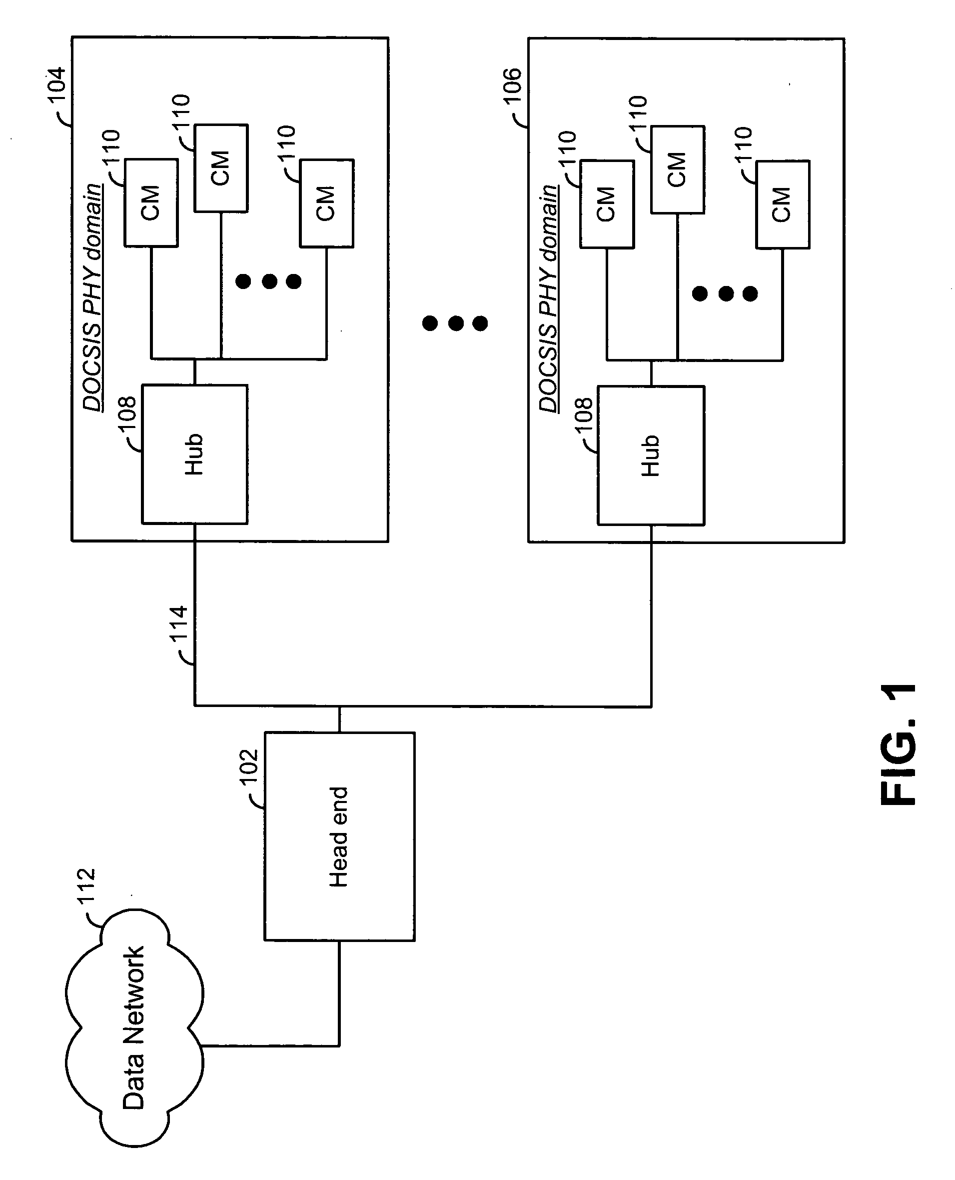
[0021]FIG. 1 is a system diagram illustrating a cable modem communication system having distributed Cable Modem Termination System (CMTS) head end components. As is illustrated in FIG. 1, the distributed CMTS includes a head end 102 and distributed hubs 108. Each of the distributed hubs 108 services a respective Data Over Cable System Interface Specification (DOCSIS) Physical Layer (PHY) domain 104 and 106. Each DOCSIS PHY domain 104 and 106 services a plurality of cable modems (CMs) 110. The head end 102 couples to the hubs 108 via a media 114. The head end 102 transfers data to, and receives data from the cable modems 100 via the hubs 108 and the media 114.
[0022] Synchronization of transmissions within the PHY domains 104 and 106 is a requirement. When supporting TDMA operations, burst transmissions (both upstream and downstream) within each DOCSIS PHY domain 104 and 106 must be sent at accurate times (100 ns level) to avoid collision. When operating in the DOCSIS 2.0 S-CDMA mode...
PUM
 Abstract
Description
Claims
Application Information
 - R&D
- Intellectual Property
- Life Sciences
- Materials
- Tech Scout
- Unparalleled Data Quality
- Higher Quality Content
- 60% Fewer Hallucinations
Browse by: Latest US Patents, China's latest patents, Technical Efficacy Thesaurus, Application Domain, Technology Topic, Popular Technical Reports.
© 2025 PatSnap. All rights reserved.Legal|Privacy policy|Modern Slavery Act Transparency Statement|Sitemap|About US| Contact US: help@patsnap.com


