Eureka AIR delivers breakthrough ideas for toughest innovation challenges, trusted by R&D personnel around the world.

In vivo imaging device and method of manufacture thereof

Inactive Publication Date: 2006-03-16
GIVEN IMAGING LTD
View PDF99 Cites 21 Cited by
  • Summary
  • Abstract
  • Description
  • Claims
  • Application Information

AI Technical Summary

Benefits of technology

[0006] In one embodiment of the present invention an in-vivo imaging device may have an oval, spherical or substantially spherical shape. In another embodiment an imaging device may include a support supporting an image sensor, an illumination source, and an antenna on a first plane of the support and a transmitter and battery support on a second plane of the support. The antenna may be combined with or attached to other elements in the in vivo imaging device so as to possibly reduce the amount of space taken up by it.

Problems solved by technology

Several factors have so far limited the extent to which the size of an imaging device can be reduced.
Another factor limiting the size reduction or space usage in imaging devices may be the size of the antenna for transmitting (and / or receiving) data such as image data.
The size of available imaging devices relative to the small openings of many body lumens may be limiting.
When certain image devices move over the surfaces of such lumens, they may, for example, tumble end over end, thus producing jumpy motion or non-continuous images.
Certain image devices may also not provide a relatively steady view of such lumens, and may not easily orient to portions of such lumens that may be desired to be imaged.

Method used


Image

  • In vivo imaging device and method of manufacture thereof
  • In vivo imaging device and method of manufacture thereof
  • In vivo imaging device and method of manufacture thereof

Examples


Embodiment Construction

[0021] In the following detailed description, numerous specific details are set forth in order to provide a thorough understanding of the invention. However, it will be understood by those skilled in the art that the present invention may be practiced without these specific details. In other instances, well-known methods, procedures, components and circuits have not been described in detail so as not to obscure the present invention.

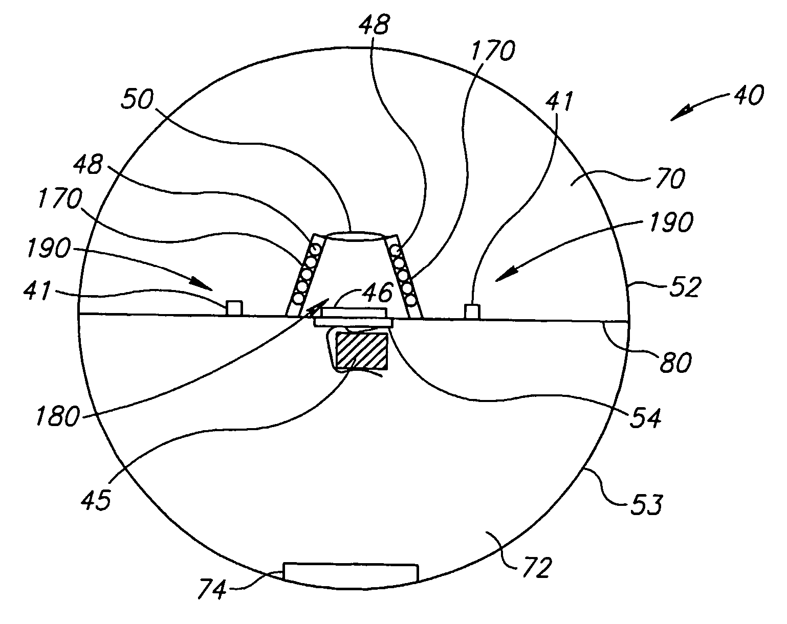
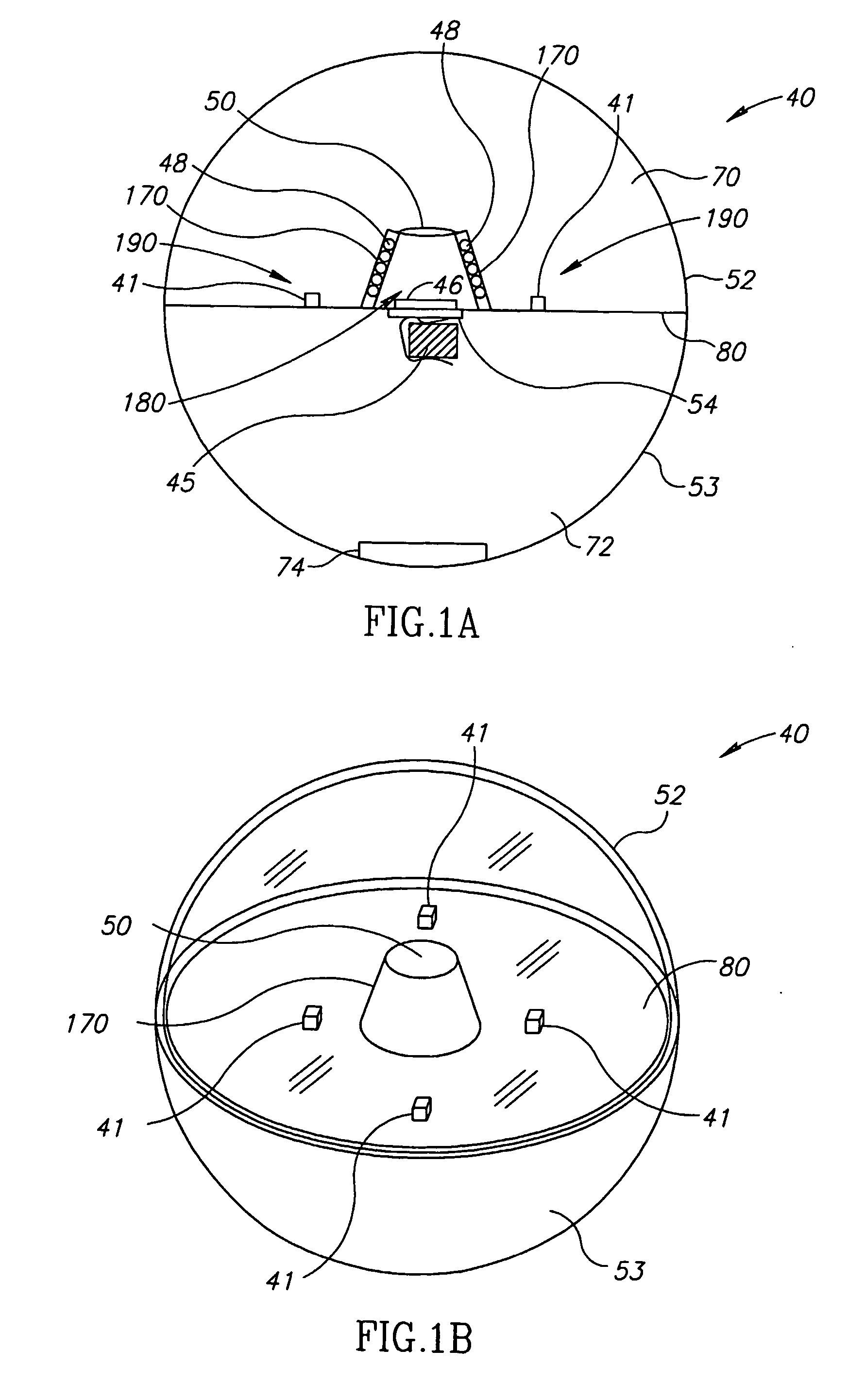
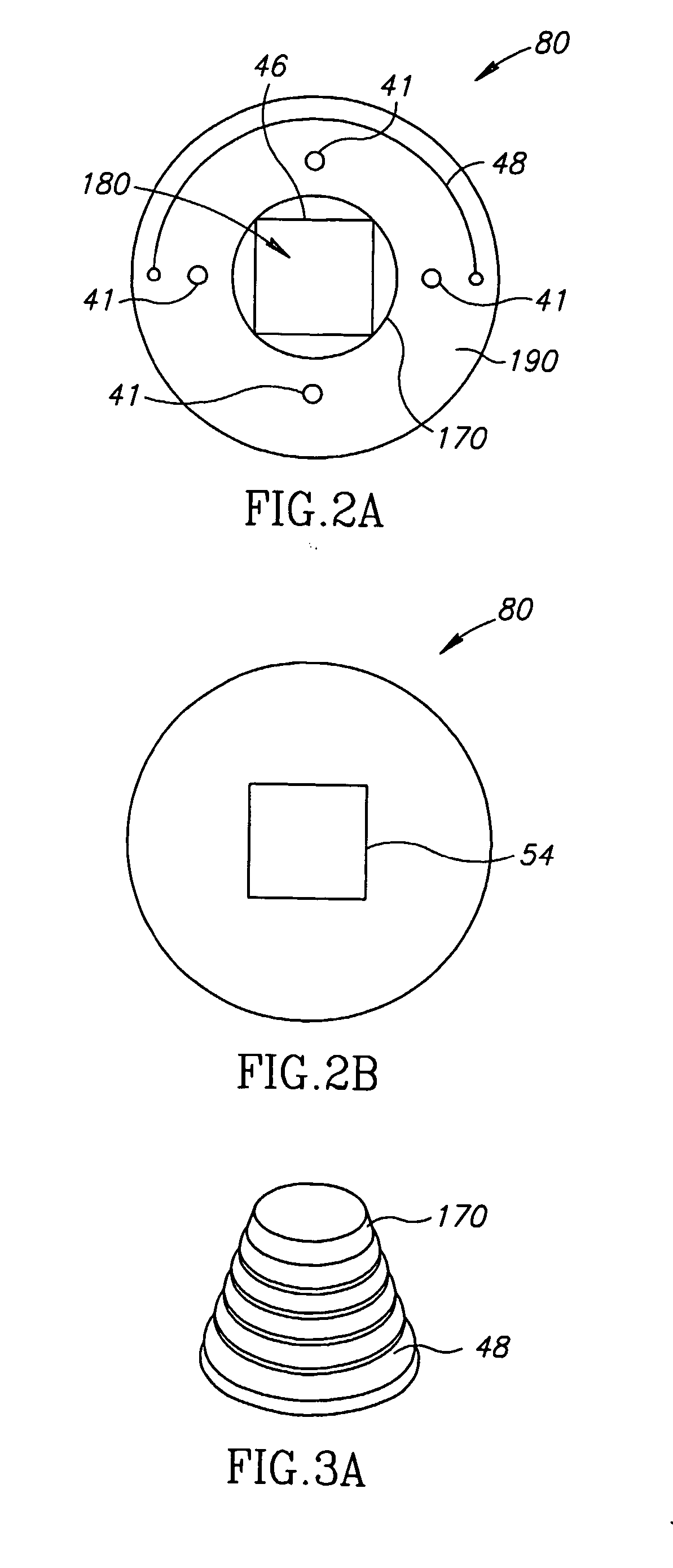
[0022] One embodiment of the device and system of the present invention may include an imaging device, which may be, for example, a capsule, for example, particularly suited for imaging the stomach or other large lumens (e.g., large intestine), although of course other suitable portions of the body may be imaged. In such applications, for example, high resolution may not be necessary, but there may for example be a need to image a wide field of view. In some embodiments, the entire organ may be imaged for example, to diagnose if a suspected pathology ex...


PUM


Abstract

A substantially spherical in vivo imaging device (40) may be used for imaging body lumens in the GI tract. The imaging device (40) may include for example a ballast or weight (74) for setting a preferred orientation of the device within the body lumen. The substantially spherical shape (52) of the in vivo imaging device (40) may facilitate capturing steady streams of imaging data in large body lumens. A method of manufacture is presented.

Description

FIELD OF THE INVENTION [0001] The present invention relates generally to in vivo imaging devices, and more specifically to an in-vivo imaging device with a spherical, ellipsoidal, oval, or similar shape. BACKGROUND OF THE INVENTION [0002] Devices and methods for performing in-vivo imaging of passages or cavities within a body are known in the art. Such devices may include, inter alia, various endoscopic imaging systems and devices for performing imaging in various internal body cavities. Some of these devices use a wireless connection to transmit image data. [0003] Several factors have so far limited the extent to which the size of an imaging device can be reduced. A first factor may be the size of the circuitry connected to the imaging sensor portion of the imaging device. A second factor may be the cumulative widths of the several components of the imaging device. Another factor limiting the size reduction or space usage in imaging devices may be the size of the antenna for transm...

Claims


Application Information

Patent Timeline
IPC IPC(8): G03B41/00G03B29/00A61B1/04A61B5/00H04N7/18
CPCA61B1/041A61B1/042A61B5/0013H04N2005/2255H04N7/183H04N23/555
Inventor IDDAN, GAVRIELJGILAD, ZVIKA
Owner GIVEN IMAGING LTD
Why Eureka
Eureka Blog
Learn More