Recording medium conveying device

a conveying device and recording medium technology, applied in printing, other printing apparatuses, etc., can solve the problems of medium lifting, image quality degradation, and low stiffness of recording medium, and achieve the effects of low stiffness, low stiffness, and high stiffness

Inactive Publication Date: 2006-03-16
KONICA MINOLTA MEDICAL & GRAPHICS INC
View PDF14 Cites 12 Cited by
  • Summary
  • Abstract
  • Description
  • Claims
  • Application Information

AI Technical Summary

Benefits of technology

[0015] According to an embodiment of the invention, since the tilt angle is changed in the ejection section corresponding to the stiffness of the recording medium, a tilt angle suitable for each recording medium can be set. Accordingly, the tilt angle can be so changed as to add tension to a recording medium with low stiffness, and the tilt angle can be so changed as to prevent lifting from the platen and to maintain flatness of the recording medium with high stiffness. Thus, even for a recording medium with different stiffness, smooth ejection can be ensured.
[0016] According to the present invention, since the entry angle or tilt angle can be so changed that tension is added to a recording medium with low stiffness, and since the entry angle or tilt angle can be so changed that lifting from the platen is prevented and flatness is maintained of a recording medium with high stiffness, conveyance accuracy and smooth ejection can be ensured for recording media with different stiffness.

Problems solved by technology

If the recording medium is lifted in this operation, the distance between the recording head and the recording medium becomes non-uniform, resulting in image quality degradation.
For example, a recording medium with high stiffness can be conveyed smoothly without being in tension because of its high stiffness, but a recording medium with low stiffness cannot be conveyed at a stable feed rate if no tension is added to the medium.
However, if a recording medium with high stiffness is conveyed on this conveyance path, there is a possibility that the recording medium is lifted from the platen because of its stiffness when it transfers from the tilted portion onto the platen.
In case of ejecting a recording medium with low stiffness, however, if no tension is added, buckling may be caused by the conveyance resistance to the recording medium when it is separated from the platen.
This buckling may cause the recording medium to rub against the discharge surface of the recording head, possibly resulting in recording medium jamming.
However, if a recording medium with high stiffness is conveyed on this conveyance path, the recording medium may be lifted from the platen because of its form maintaining force due to the stiffness when the recording medium hangs down, and may rub against the discharge surface of the recording head, possibly resulting in recording medium jamming.

Method used


Image

  • Recording medium conveying device
  • Recording medium conveying device
  • Recording medium conveying device

Examples


first embodiment

The First Embodiment

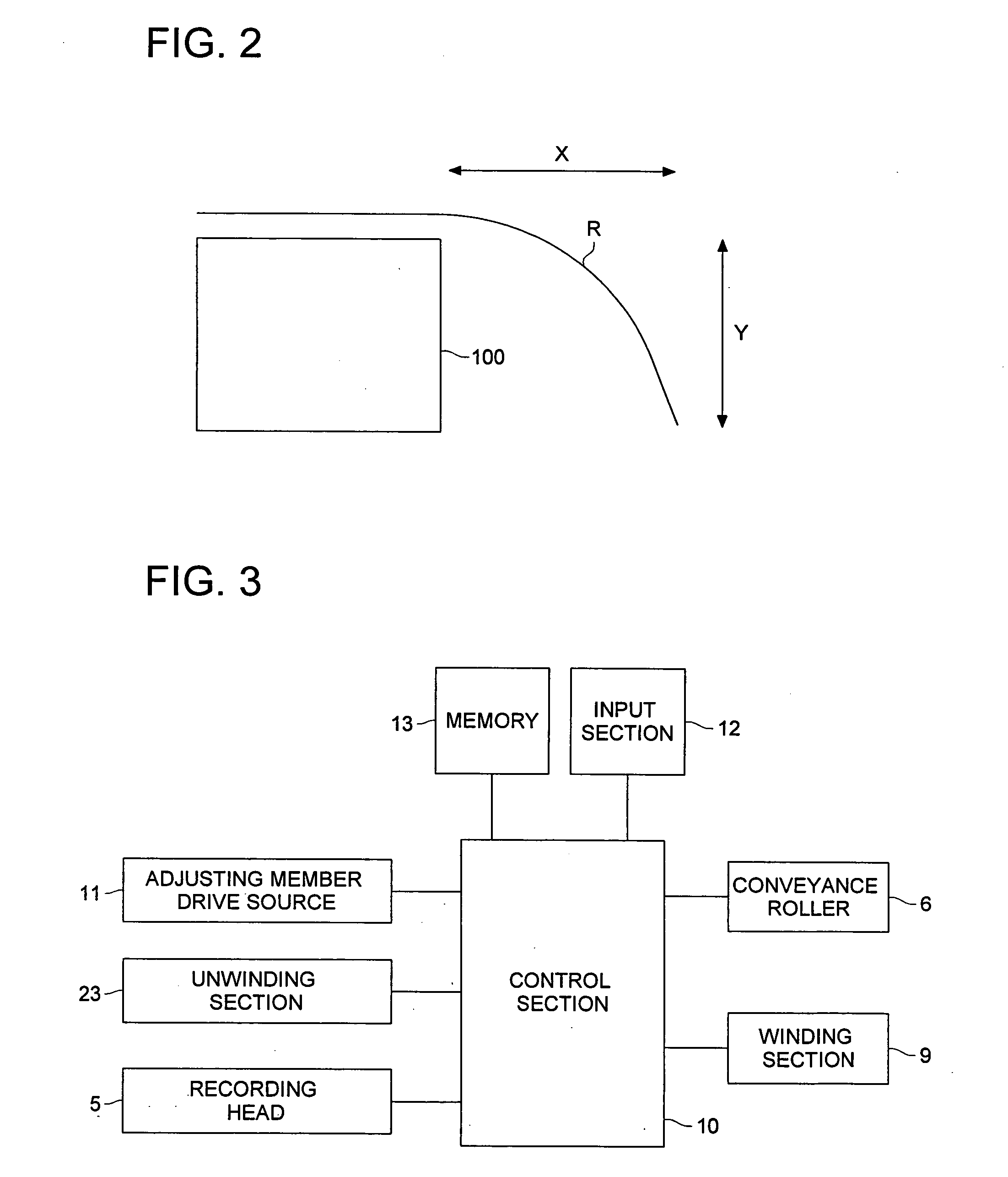
[0032] The first embodiment is the recording medium conveying device equipped with an entrance section in which the entry angle with the platen, at which the recording medium enters the conveyance roller, is freely changeable corresponding to the stiffness of the recording medium, which is described hereunder.

[0033] The recording medium conveying device of the present invention is described hereunder, using the attached figures.

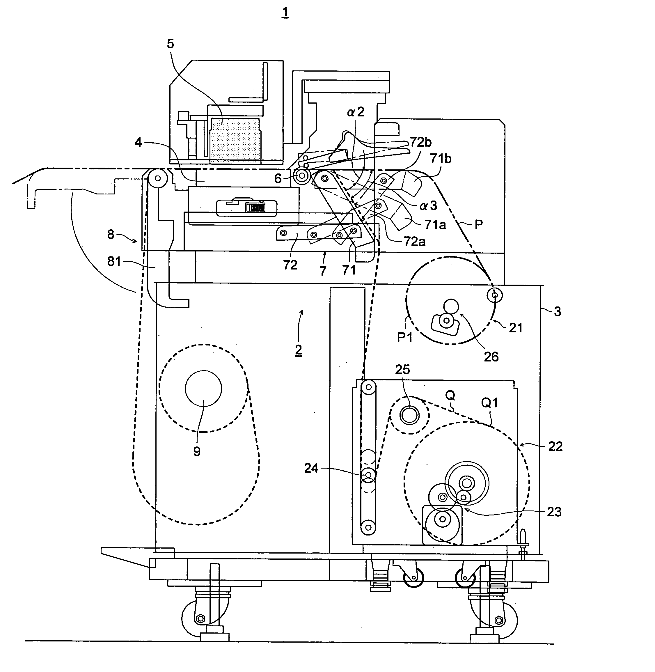
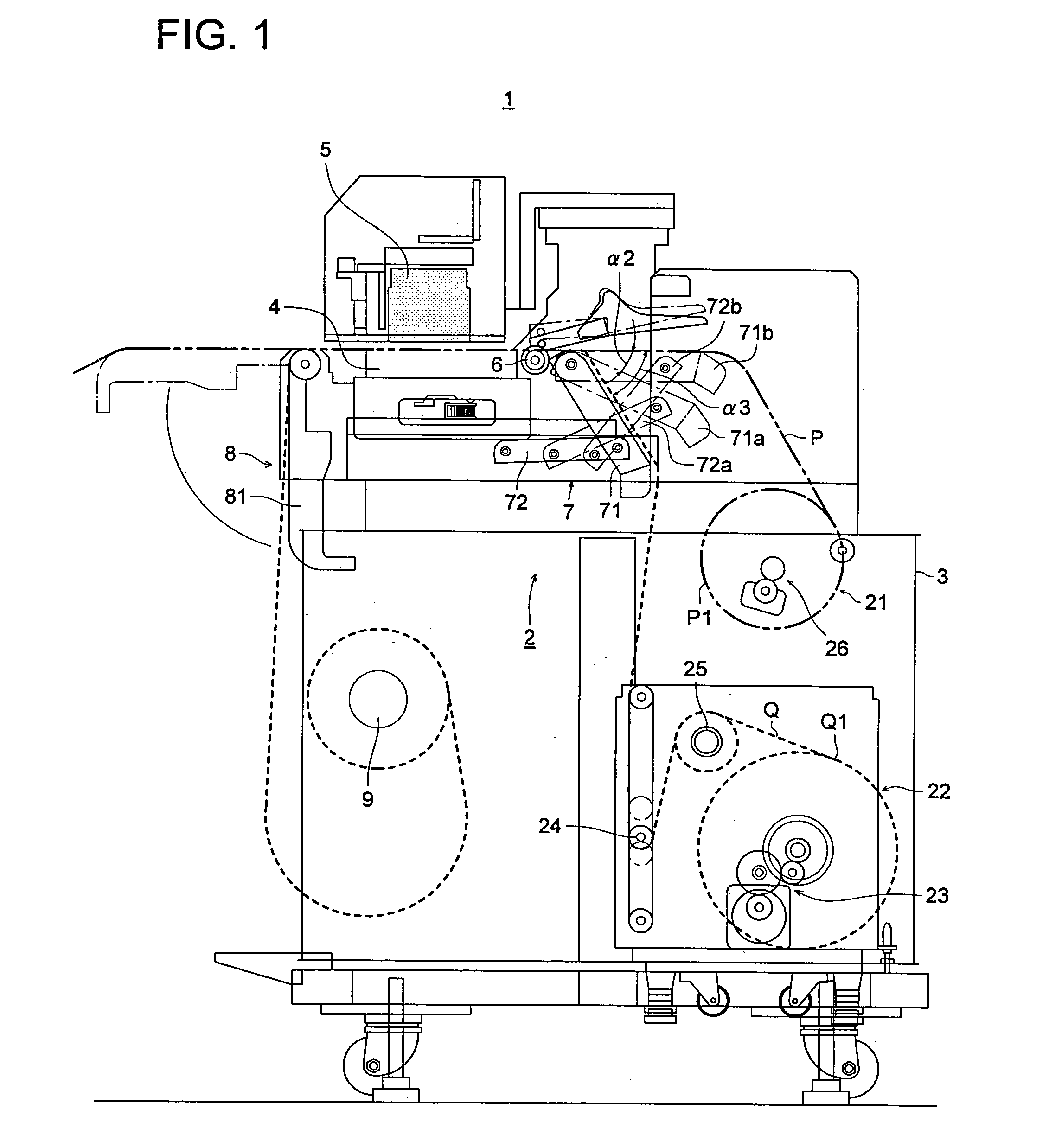
[0034]FIG. 1 is the image recording apparatus 1 equipped with the recording medium conveying device of this embodiment. As shown in FIG. 1, the image recording apparatus 1 is equipped with a case 3 that encloses the recording medium conveying device 2, platen 4 that is supported above the case 3 and supports the recording medium P or Q horizontally from beneath, and recording head 5 that is located above the platen 4 and emits ink onto the recording medium P or Q supported by the platen 4.

[0035] The recording medium conveying device 2 h...

second embodiment

The Second Embodiment

[0057] The second embodiment is the recording medium conveying device equipped with the ejection section in which the tilt angle in the ejection path is freely changeable corresponding to the stiffness of the recording medium, which is described hereunder.

[0058] Downstream of the platen 4 of the recording medium conveying device 2, there is provided an ejection section 8 that forms an ejection path of the recording media P and Q. The ejection section 8 is equipped with an ejection guide 81 that supports the recording medium P or Q from below and forms the ejection path, and an ejection guide drive source 82 that swings the ejection guide 81 around its one end on the platen 4 side as a swinging axis (see FIG. 3).

[0059] The ejection guide 81 is swung by the ejection guide drive source so that its position can be switched to two positions: the horizontal position (sold line in FIG. 1) or vertical position (alternate long and short dash line in FIG. 1). Accordingl...


PUM


Abstract

A recording medium conveying device comprising: a master roll holder to hold a master roll of a recording medium; a platen to support the recording medium supplied from the master roll holder in an image recording section; a conveyance roller positioned upstream of the platen to convey the recording medium by adding driving force to the recording medium and a guide positioned near the platen to guide the recording medium, wherein the guide changes an angle of the recording medium against the platen according to a stiffness of the recording medium.

Description

[0001] This application is based on Japanese Patent Application Nos. 2004-269868 and 2004-269881 filed on Sep. 16, 2004 in Japanese Patent Office, the entire content of which is hereby incorporated by reference. BACKGROUND OF THE INVENTION [0002] The present invention relates to a recording medium conveying device, particularly to a recording medium conveying device which conveys a recording medium in accordance with image recording. [0003] An image recording apparatus such as an ink jet printer is equipped with a recording medium conveying device which conveys a recording medium in accordance with image recording (see the Patent Documents 1 and 2, for examples.) The recording medium conveying device has a master roll holding section that holds the master roll of the recording medium upstream of the platen which is positioned in an image recording area of the image recording apparatus, and it also has an ejecting section that ejects the recording medium after recording an image down...

Claims


Application Information

Patent Timeline
Patent Type & Authority Applications(United States)
IPC IPC(8): B41J15/04B41J15/16B41J15/18
CPCB41J11/0005B41J11/005B41J15/18B41J15/046B41J15/16B41J11/006
Inventor HAYAKAWA, KAZUSHI
Owner KONICA MINOLTA MEDICAL & GRAPHICS INC
Why Eureka
Try Eureka