Apparatus and method of detecting wear in an abradable coating system

a coating system and abradable technology, applied in additive manufacturing apparatus, non-positive displacement fluid engines, liquid fuel engine components, etc., can solve the problems of difficult to obtain real-world operating environment data, designers and operators have very little information regarding the internal status of turbine engine components during operation, and superalloy materials cannot withstand extended exposure to hot combustion gas of current generation gas turbine engines withou

Inactive Publication Date: 2006-03-16
SIEMENS ENERGY INC
View PDF43 Cites 83 Cited by
  • Summary
  • Abstract
  • Description
  • Claims
  • Application Information

AI Technical Summary

Problems solved by technology

However, even superalloy materials are not able to withstand extended exposure to the hot combustion gas of a current generation gas turbine engine without some form of cooling and / or thermal insulation.
Such real world operating environment data is very difficult to obtain, particularly for components that move during the operation of the engine, such as the rotating blades of the turbine.
Despite the extreme sophistication of modern turbine engines, such as gas turbines for generating electrical power or aircraft engines for commercial and military use, designers and operators have very little information regarding the internal status of the turbine engine components during operation.
This is due to the harsh operating conditions, which have prevented the use of traditional sensors for collecting reliable information of critical engine components.
The lack of specific component information makes early failure detection very difficult, often with the consequence of catastrophic engine failure due to abrupt part failure.
This results in inefficient utilization, unnecessary downtime and an enormous increase in operating cost.
This approach is highly subjective and only allows for determining already severe situations with an engine.
It does not provide indications of impending damage or insight into the progression of events leading up to and causing engine damage due to component degradation or failure.
Instrumenting components using this technique is expensive, which is a barrier to instrumenting a large number of components within a single turbine.
Further, the wire leads and data transfer is frequently poor, which can result in costly repairs and flawed data analysis.
Using thermocouples for temperature measurements in the gas path of a turbine may be disadvantageous because it only provides feedback to an operator that a temperature change has occurred in the gas path.
This correlation is difficult and time consuming to derive to within a reasonable degree of certainty and needs to be done on an engine-by-engine basis taking into account turbine operation conditions.
When a temperature differential is measured, it is difficult, if not impossible, to predict what the problem is or where it is located.
Such diagnostic monitoring systems can only predict or estimate specific component conditions and do not collect data from or provide any analysis with respect to the actual condition of a specific component itself.
In this respect, conventional methods of predicting component failure for gas turbines and of scheduling maintenance have not been entirely accurate or optimized.
The traditional “duty cycle” used for predictive maintenance does not reflect real operational conditions, especially off-design operations.
For example, elevated temperatures and stresses within the turbine, and aggressive environmental conditions may cause excessive wear on components in the turbine beyond that predicted with the standard design duty cycle.
In either event, the standard design duty cycle model for predicting preventive maintenance does not reliably indicate the actual wear and tear experienced by gas turbine components.
None of these techniques provide accurate information with respect to the actual condition of a specific component or component coating, which may lead to unnecessary repair, replacement or maintenance being performed causing a significant increase in operating costs.

Method used


Image

  • Apparatus and method of detecting wear in an abradable coating system
  • Apparatus and method of detecting wear in an abradable coating system
  • Apparatus and method of detecting wear in an abradable coating system

Examples


Embodiment Construction

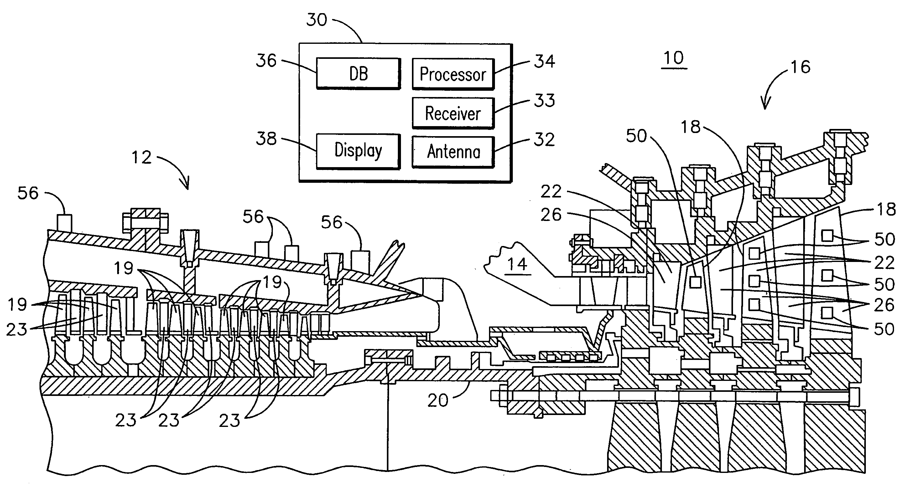
[0033] Embodiments of the present invention use sensors, such as a planar proximity sensor, embedded within coatings, such as an abradable coating system, or installed on or within a surface of a component to determine the wear behavior of the coating or component when contacted by another component. Abradable coating systems may be used for gas path clearance control, which influences power output and efficiency of a gas turbine such as the exemplary combustion turbine of FIG. 1. The abradable coating system abrades when contacted by another component, such as a plurality of rotating blades 18 secured to a rotatable central shaft 20 mounted within turbine 16.

[0034]FIG. 1 illustrates an exemplary combustion turbine 10 such as a gas turbine used for generating electricity as will be recognized by those skilled in the art. Embodiments of the invention may be used with combustion turbine 10 or in numerous other operating environments and for various purposes as will be recognized by t...


PUM

PropertyMeasurementUnit
operating temperaturesaaaaaaaaaa
thicknessaaaaaaaaaa

Abstract

A component for use in a combustion turbine (10) is provided that includes a substrate (212) and an abradable coating system (216) deposited on the substrate (212). A planar proximity sensor (250) may be deposited beneath a surface of the abradable coating system (216) having circuitry (252) configured to detect intrusion of an object (282) into the abradable coating system (216). A least one connector (52) may be provided in electrical communication with the planar proximity sensor (250) for routing a data signal from the planar proximity sensor (250) to a termination location (59). A plurality of trenches (142) may be formed at respective different depths below the surface of the abradable coating system (216) with a planar proximity sensor (250) deposited within each of the plurality of trenches (142). A processing module (34) may be programmed for receiving data from the planar proximity sensor (250) and calculating a clearance between a row of blades (18,19) within a combustion turbine and the planar proximity sensor (250). The processing module (34) may control a clearance between the row of blades (18) and a ring segment (284) based on data received from the planar proximity sensors (250).

Description

CROSS REFERENCE TO RELATED APPLICATIONS [0001] This application is a continuation-in-part of pending U.S. patent application Ser. No. 11 / 122,566 filed May 5, 2005, which claims the benefit of Provisional Patent Application No. 60 / 581,662 filed on Jun. 21, 2004, which is also a continuation-in-part of pending U.S. patent application Ser. No. 11 / 018,816 filed Dec. 20, 2004, which is a continuation-in-part of U.S. patent application Ser. No. 10 / 252,236 filed Sep. 23, 2002, now U.S. Pat. No. 6,838,157 all of which are incorporated herein by reference.FIELD OF THE INVENTION [0002] The present invention relates generally to monitoring parameters of operating environments and particularly to an apparatus and method of determining wear behavior of an abradable coating system deposited on components within an operating environment such as a gas turbine engine. BACKGROUND OF THE INVENTION [0003] Gas combustion turbines are used for a variety of applications such as driving an electric generat...

Claims


Application Information

Patent Timeline
Patent Type & Authority Applications(United States)
IPC IPC(8): F04D29/00B32B9/04F01D17/02F01D17/08F01D21/00
CPCC23C4/18Y10T428/24926F01D17/08F01D21/003F01D21/04F01D25/24F23M5/00F23M11/00F23R3/007G01K7/028G01K13/02G01K17/20G01K2205/04G01N3/56F05D2230/90F05D2260/80F05D2230/30C23C28/3215C23C28/3455C23C24/04F01D17/02B33Y80/00F04D27/001F04D29/324F04D29/526F04D29/542
Inventor SABOL, STEPHEN M.SUBRAMANIAN, RAMESHKULKARNI, ANAND A.
Owner SIEMENS ENERGY INC
Why Eureka
Try Eureka