Direct liquid fuel cell and method of peventing fuel decomposition in a direct liquid fuel cell

a liquid fuel cell and direct technology, applied in the direction of fuel cells, portable application adaption, sustainable buildings, etc., can solve the problems of methanol toxicity, poor discharge characteristics at room temperature, energy loss, etc., and achieve the effect of reducing or substantially preventing the decomposition of fuel

Inactive Publication Date: 2006-03-16
MORE ENERGY
View PDF99 Cites 14 Cited by
  • Summary
  • Abstract
  • Description
  • Claims
  • Application Information

AI Technical Summary

Benefits of technology

[0040] In a still further aspect, the method may comprise limiting or substantially preventing the ability of the gas that is generated by the initial fuel decomposition to flow away from the anode. This may be accomplished, for example, by at least one membrane that is arranged on the side of the anode that faces the fuel chamber of the fuel cell.
[0041] The present invention further provides a method for reducing or substantially preventing fuel decomposition at an anode of a direct liquid fuel cell which uses a fuel that generates a gas when undergoing said decomposition. The method comprises arranging, between the fuel chamber of the fuel cell and the anode, one or more of at least one porous structure, at least one mesh structure, and at least one membrane, and allowing the gas to be formed during an initial decomposition of the fuel in the fuel cell, whereby the gas restricts or substantially prevents contact between the fuel and the anode.

Problems solved by technology

The main disadvantages of such Direct Methanol Fuel Cells (DMFCs) are the toxicity of methanol and the very poor discharge characteristics at room temperature.
As a result, DMFCs are not generally used for portable electronics applications and the like.
The main problem associated with hydride and borohydride fuels is a spontaneous decomposition of the fuel on the (active layer of the) anode surface which is accompanied by a generation of hydrogen, usually in the form of microbubbles, e.g., bubbles of from about 0.01 to about 2 mm in size.
Hydride and borohydride decomposition at the anode of a DLFC results in several technical problems, in particular, energy loss, destruction of the anode active layer, and decreasing safety characteristics.

Method used


Image

  • Direct liquid fuel cell and method of peventing fuel decomposition in a direct liquid fuel cell
  • Direct liquid fuel cell and method of peventing fuel decomposition in a direct liquid fuel cell
  • Direct liquid fuel cell and method of peventing fuel decomposition in a direct liquid fuel cell

Examples


example 1

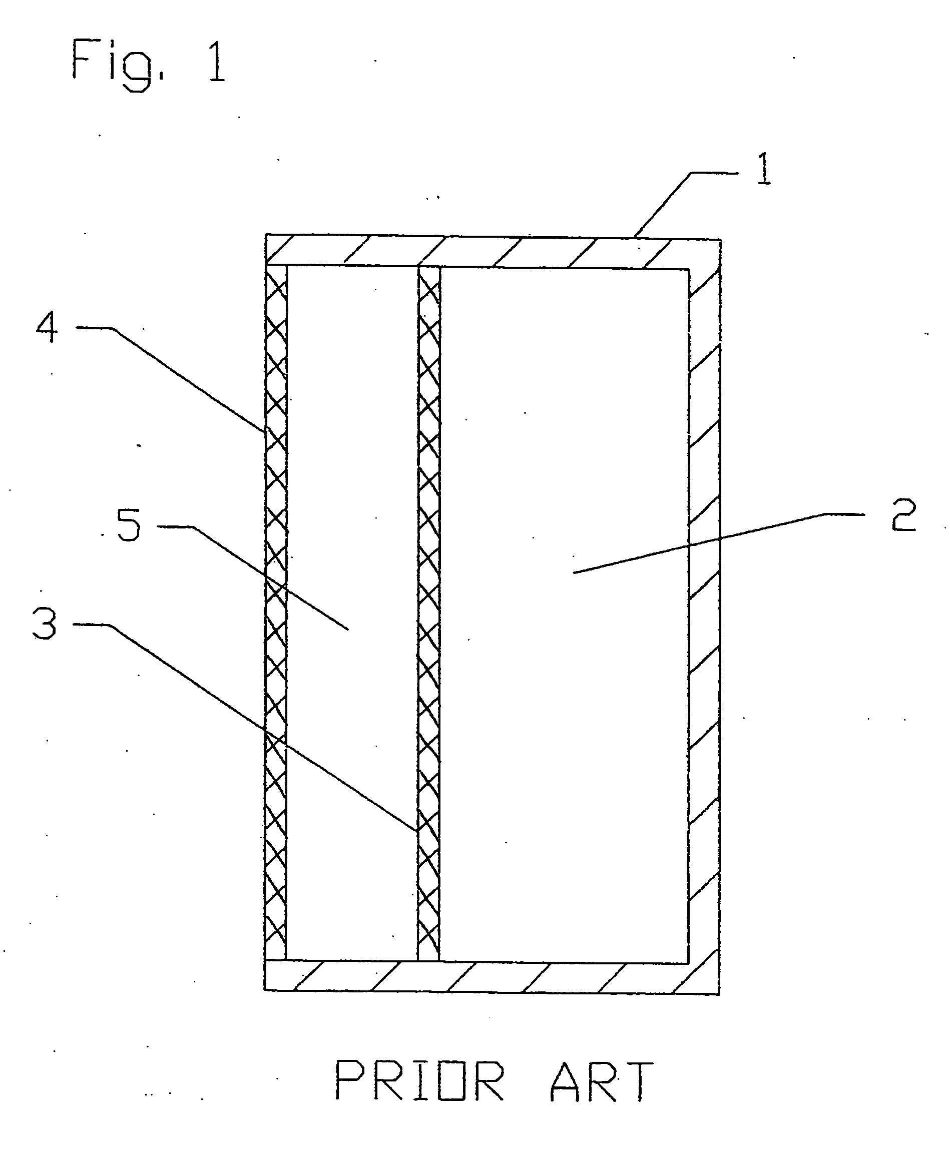
[0085] A conventional DLFC of the type shown in FIG. 1 with the following parameters was employed for testing:

Area of anode and cathode=each 45 cm2 (62 mm×73 mm); [0086] Thickness or width of electrolyte chamber=4 mm; [0087] Volume of electrolyte in the electrolyte chamber=18 cm3; [0088] Thickness or width of fuel chamber=20 mm; and [0089] Volume of fuel in the fuel chamber=90 cm3.

[0090] The DLFC was filled with a borohydride fuel and tested under the following conditions: [0091] Full time of test=20 hours; [0092] Unloading regime=open circuit.

[0093] In this test, the maximum gas productivity was 15 cm3 / min. As can be seen from FIG. 4, the generation of hydrogen begins to decrease after about 60 minutes, but continues over the full 20 hours of the test.

example 2

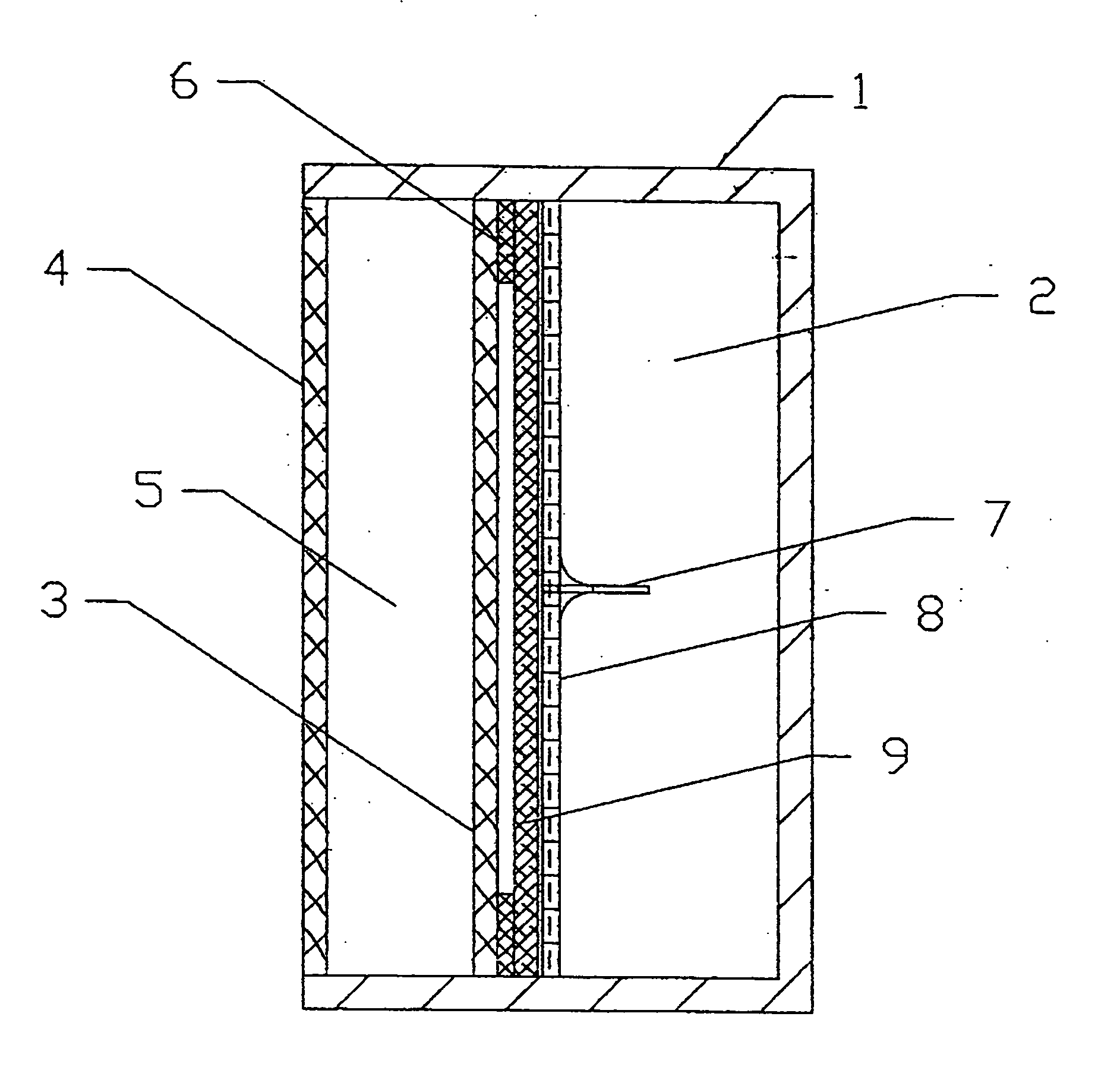
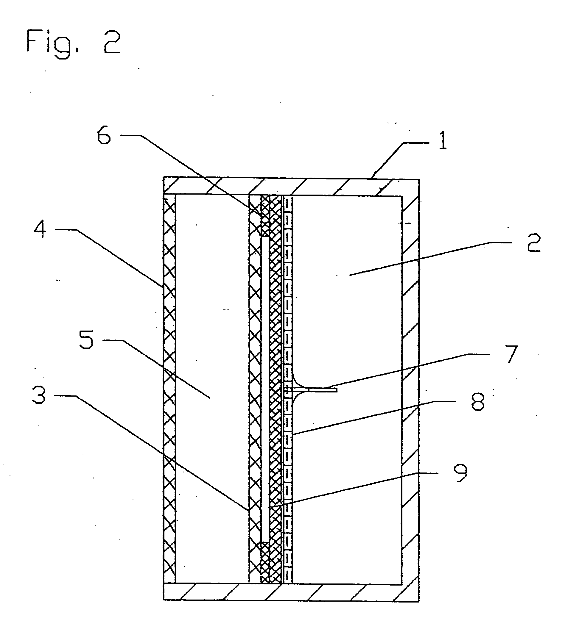
[0094] A DLFC according to the present invention of the type shown in FIG. 2 with the following parameters was employed for testing:

Area of anode and cathode=each 45 cm2 (62 mm'73 mm); [0095] Thickness or width of electrolyte chamber=4 mm; [0096] Volume of electrolyte in the electrolyte chamber=18 cm3; [0097] Thickness or width of fuel chamber=20 mm; [0098] Volume of fuel in the fuel chamber=90 cm3; [0099] Thin film Teflon frame-seal thickness=50 μm; [0100] Stainless steel capillary needle length=7 mm, Inside Diameter=320 μm; [0101] Stainless steel micromesh special membrane with cells=53 μm; and [0102] Polypropylene wattled net spacer material with cells of 2 mm×3 mm and with a thickness=1 mm.

[0103] The DLFC was filled with a borohydride fuel and tested under the following conditions: [0104] Full time of test=20 hours; [0105] Unloading regime=open circuit.

[0106] In this test, the time until the space between the anode 3 and the special membrane 8 was filled was 45 seconds. As ca...


PUM

PropertyMeasurementUnit
sizeaaaaaaaaaa
sizeaaaaaaaaaa
thicknessaaaaaaaaaa

Abstract

A direct liquid fuel cell includes a cathode, an anode, a fuel chamber, and at least one membrane arranged between the anode and the fuel chamber. The membrane is structured and arranged to allow gas which is formed on or in the vicinity of the surface of the anode which faces the fuel chamber to accumulate adjacent to the anode at least to a point where the accumulated gas substantially prevents a direct contact between the anode and the liquid fuel. A method of preventing or reducing fuel decomposition in the fuel cell is also disclosed. This Abstract is not intended to define the invention disclosed in the specification, nor intended to limit the scope of the invention in any way.

Description

CROSS-REFERENCE TO RELATED APPLICATIONS [0001] The present application is a continuation-in-part of U.S. application Ser. No. 10 / 941,020 filed Sep. 15, 2004, the disclosure of which is expressly incorporated by reference herein in its entirety.BACKGROUND OF THE INVENTION [0002] 1. Field of the Invention [0003] The present invention relates to a Direct Liquid Fuel Cell (DLFC) which uses a hydride fuel and also relates to specifically preventing or at least substantially reducing the generation of hydrogen caused by a decomposition of the hydride fuel at the anode of the fuel cell when the DLFC is under no or only a low load. [0004] A hydride fuel decomposition reaction at the anode of the fuel cell generates hydrogen during the period where the fuel cell is under no or only a low load. The invention thus also provides a method which uses the generated hydrogen to provide a separation layer between the anode and the liquid fuel. In this way, the fuel is substantially prevented from co...

Claims


Application Information

Patent Timeline
Patent Type & Authority Applications(United States)
IPC IPC(8): H01M8/00
CPCH01M8/0232Y02B90/18H01M8/0284H01M8/04186H01M8/04201H01M8/0637H01M8/065H01M8/083H01M8/1009H01M8/22H01M8/225H01M2250/30H01M2300/0014Y02E60/521H01M8/0273Y02B90/10Y02E60/50H01M8/04
Inventor FINKELSHTAIN, GENNADIKATSMAN, YURISADON, IIANESTRIN, MARKLITVINOV, ALEXANDERILYUSHIN, BORISCHINAK, ALEXANDERBLUVSTEIN, ALEXANDERLERNER, MICHAEL
Owner MORE ENERGY
Why Eureka
Try Eureka