Cuff for blood pressure monitor

Inactive Publication Date: 2006-03-16
OMRON HEALTHCARE CO LTD
View PDF4 Cites 11 Cited by
  • Summary
  • Abstract
  • Description
  • Claims
  • Application Information

AI Technical Summary

Benefits of technology

[0018] With this configuration, wrinkles of the fluid bag, caused when the pressurized air is introduced therein, come into contact with the air-permeable member arranged inside the inflated / deflated space. This prevents further increase in size of the wrinkles, and thus, the wrinkles are distributed over the entire region of the fluid bag. In addition, with provision of the air-permeable member that is a porous member, an air passage through which the fluid flows from one end to the other end of the fluid bag in its winding direction is secured, so that the fluid bag is inflated uniformly over the entire region. Accordingly, stable avascularization performance is achieved, and accurate and stable measurement of the blood pressure values is ensured. Herein, the winding direction of the fluid bag with respect to the living body refers to the direction in which the fluid bag wound to surround the living body extends in the fitted state of the cuff. It coincides with the circumferential direction of the cuff wound around the living body in the fitted state.
[0020] Thus, by arranging the air-permeable member uniformly through the entire region of the inflated / deflated space, it is possible to uniformly inflate the fluid bag over the entire region more reliably.
[0022] Even in the case where the air-permeable member contained in the fluid bag is formed in a ladder shape in two dimensions, it is possible to uniformly inflate the fluid bag over the entire region in the winding direction of the fluid bag.
[0024] With this configuration, it is readily possible to arrange the air-permeable member inside the fluid bag, and accordingly, the cuff for a blood pressure monitor having the above-described configuration can be fabricated with ease.
[0026] Thus, by using the sponge formed by continuous foaming as the air-permeable member, the cuff for a blood pressure monitor having the above-described configuration can be fabricated in a simple and inexpensive manner.
[0027] According to the present invention, it is possible to uniformly inflate the fluid bag over the entire region when the pressurized air is introduced therein. As such, stable avascularization performance is achieved at the time of measurement, and accordingly, accurate and stable measurement of the blood pressure values is enabled.

Problems solved by technology

The problem at this time is occurrence of wrinkles S1 at the surface of air bag 10E inflated by the pressurized air.
Occurrence of wrinkles S1 leads to degradation of avascularization performance by air bag 10E, disadvantageously decreasing the accuracy in measurement of blood pressure values.
In this case, it will not be possible to sufficiently inflate air bag 10E over the entire region, and thus, the blood pressure values measured will include considerable errors.
With the above-described techniques, however, wrinkles are caused to occur locally in prescribed positions of the air bag, which may rather increase the probability of occurrence of bending in the relevant positions.
If such bending occurs in the air bag, the above-described flow of the air in the inflated / deflated space will be blocked, making it difficult to uniformly inflate the air bag over the entire region.
In such a case, it is not possible to uniformly and stably press the measurement site, thereby causing measurement errors.
The technique is not for preventing bending of a large-sized air bag for avascularization that is fitted to surround the measurement site.
It does not function effectively for the cuff configured with one air bag that is used both for avascularization and for detection of pulse waves.
Thus, provision of a hard core member inside the air bag would considerably adversely affect the fitting of the cuff.
Further, although the above-described technique may prevent bending of a small-sized air bag for detecting pulse waves, it would not be able to suppress occurrence of large wrinkles or bending of a large-sized air bag for avascularization caused when the pressurized air is introduced therein.
Thus, in the case where big wrinkles or bending occur locally in the air bag for avascularization, it is not possible to uniformly press the measurement site over the entire region, resulting in degradation of avascularization performance.
Accordingly, the problem of degradation of accuracy in measurement of the blood pressure values is yet to be solved.

Method used


Image

  • Cuff for blood pressure monitor
  • Cuff for blood pressure monitor
  • Cuff for blood pressure monitor

Examples


Embodiment Construction

[0037] Hereinafter, an embodiment of the present invention will be described with reference to the drawings. In the following embodiment, a cuff for use in a wrist blood pressure monitor using the wrist as the measurement site for measurement of blood pressure values will be explained by way of example.

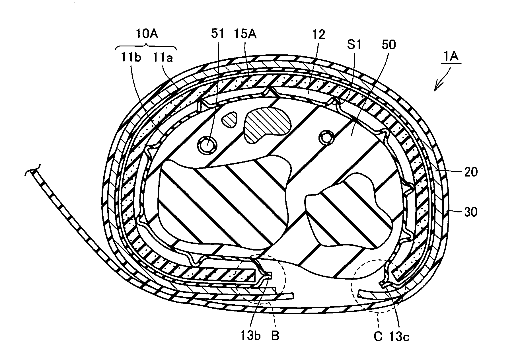
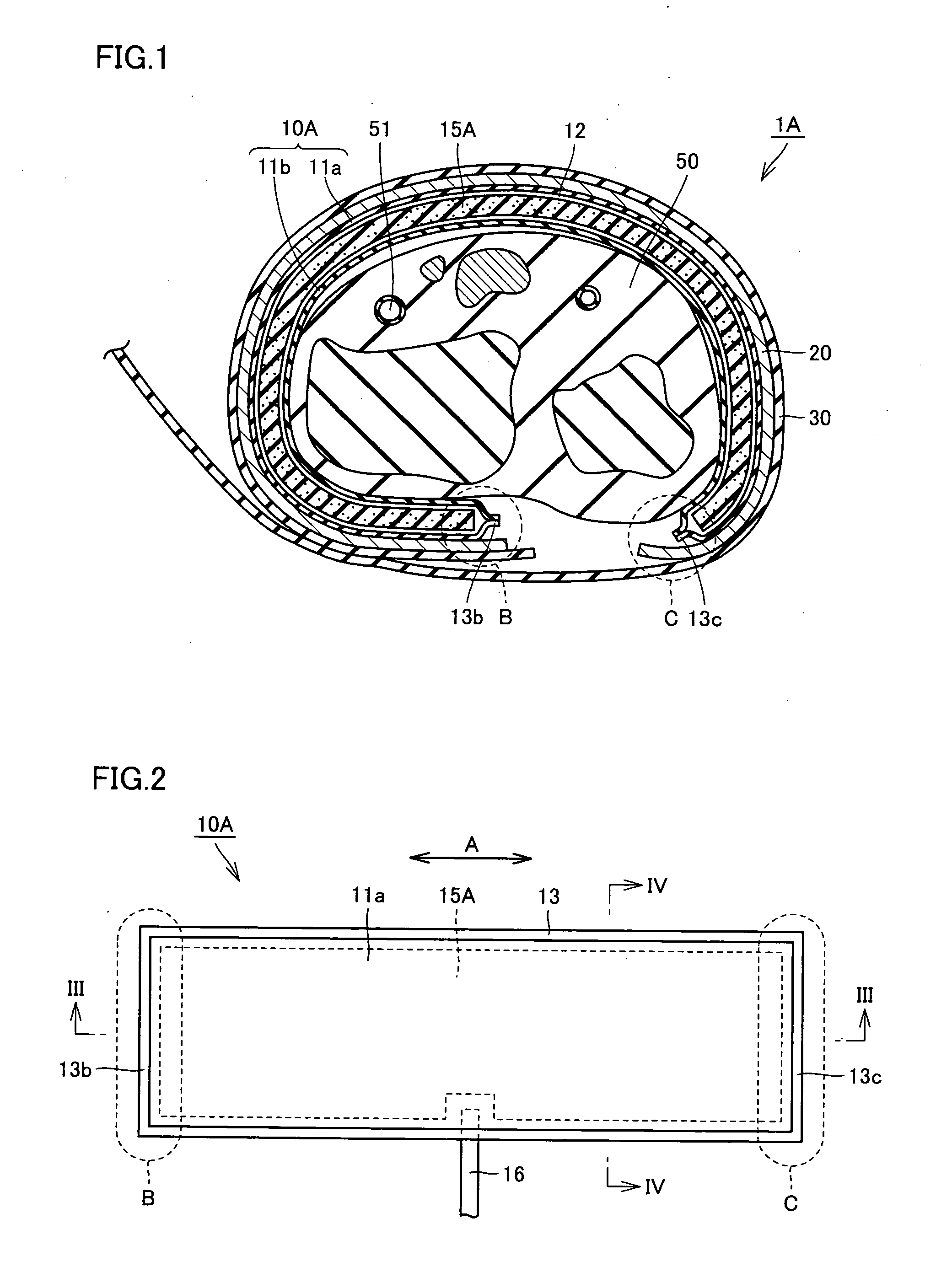
[0038]FIG. 1 is a schematic cross sectional view of a cuff for a blood pressure monitor according to an embodiment of the present invention, showing the state where the cuff is wound around a wrist. As shown in FIG. 1, the cuff 1A for a blood pressure monitor of the present embodiment includes, among others, an air bag 10A that is a fluid bag, a curled elastic member 20 that is an elastic member located on the outside of air bag 10A and wound in an approximately cylindrical shape radially changeable in size, and a fastening band 30 for securing cuff 1A to the living body. Air bag 10A has its outer peripheral surface fixed to the inner peripheral surface of curled elastic member 20. T...


PUM


Abstract

A cuff for a blood pressure monitor includes an air bag having an inflated / deflated space permitting a fluid to come in and out, and a sponge that is arranged inside the inflated / deflated space to extend substantially continuously from one end to the other end of the air bag in its winding direction. With this configuration, a cuff for a blood pressure monitor permitting the air bag to be inflated uniformly over the entire region when the air is introduced therein is achieved.

Description

BACKGROUND OF THE INVENTION [0001] 1. Field of the Invention [0002] The present invention relates to a cuff for a blood pressure monitor wound around a measurement site of a living body, such as a wrist, an upper arm or the like, for measurement of blood pressure values. [0003] 2. Description of the Background Art [0004] To measure a blood pressure value, generally, a cuff provided with a fluid bag for pressing an artery located within a living body is wound around the body surface, and arterial pressure pulse waves caused in the artery by inflation / deflation of the fluid bag are detected to measure the blood pressure value. Here, the cuff refers to a band-shaped structure having a bladder, which can be wound around a part of a living body, for use in measurement of arterial pressure of an upper limb, a lower limb or the like by introducing fluid such as gas or liquid into the bladder. Thus, the cuff represents the concept including the fluid bag as well as members for winding the f...

Claims


Application Information

Patent Timeline
IPC IPC(8): A61B5/02
CPCA61B5/02233A61B5/022
Inventor KISHIMOTO, HIROSHISANO, YOSHIHIKOKARO, HIROMICHI
Owner OMRON HEALTHCARE CO LTD
Why Eureka
Try Eureka