Tubing hanger with ball valve in production string

Inactive Publication Date: 2006-03-23
STREAM FLO INDS
View PDF30 Cites 20 Cited by
  • Summary
  • Abstract
  • Description
  • Claims
  • Application Information

AI Technical Summary

Problems solved by technology

However, running of a back pressure valve or plug in the tubing hanger is a complex and expensive task, particularly if the well is remotely located.
A few patents describe ball valves in the production bore of a tubin

Method used


Image

  • Tubing hanger with ball valve in production string
  • Tubing hanger with ball valve in production string
  • Tubing hanger with ball valve in production string

Examples


Example

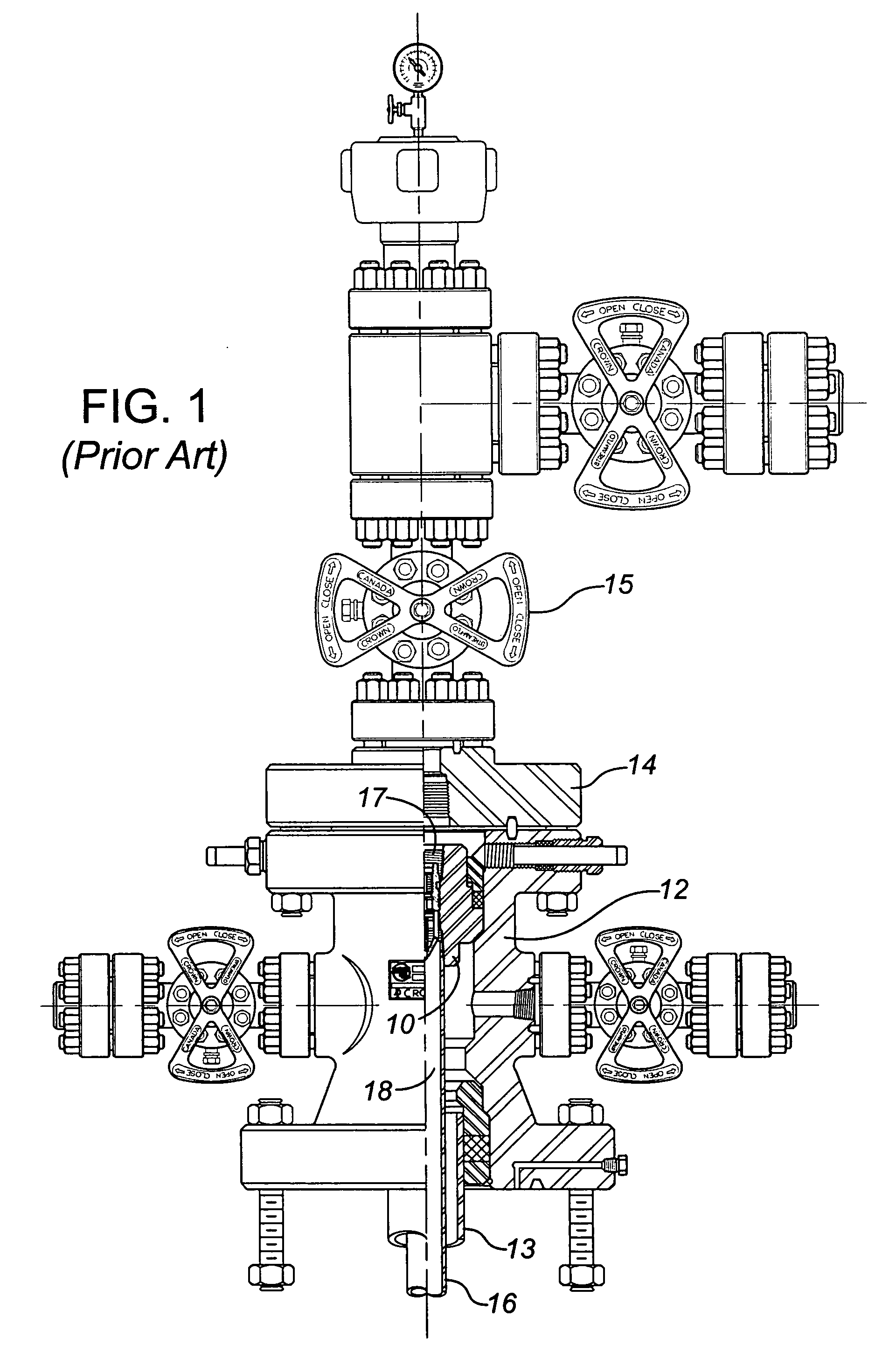
[0026]FIG. 1 is included to show a tubing head / tubing hanger arrangement of the prior art, in which a tubing hanger 10 is sealed and supported within a wellhead housing, here shown as a tubing head 12. The tubing head 12 is adapted at its lower end for connection to the next wellhead member, typically a casing head (not shown) to suspend casing 13. The tubing head 12 is shown connected at its upper end to a tubing head flange adaptor 14, and Christmas tree components 15 (shown in order in FIG. 1 is a master valve, a flow tee with a wing valve and a top connector). The Christmas tree components 15 are known in the art and will typically include one or more valves and blow out preventer (BOP) stack). The tubing hanger 10 is adapted at its lower end to suspend production tubing 16. Shown in FIG. 1 is a back pressure valve 17, which must be run in as described above when one wishes to close off the production bore 18 at the tubing hanger 10. As indicated above, running and retrieving a ...


PUM


Abstract

The invention provides a wellhead assembly including a wellhead housing supporting a tubing hanger within its central bore and forming a housing stem port through its outer wall to the central bore. The tubing hanger has a side stem port formed through its body intermediate its upper and lower ends providing access to the central bore of the hanger and being aligned with the housing stem port. The tubing hanger includes a ball valve member having a spherical exterior surface sealed and seated from above and below within the central bore of the hanger. The ball valve member forms a through port extending therethrough aligned with the production bore, and is rotatable in its seated position between open and closed positions with the through port being aligned with the production bore when in the open position. A slot in the exterior surface of the ball valve member if formed proximate the stem port. A ball stem assembly is sealed for axial rotation in both the stem port of the body and the housing stem port of the wellhead housing, one end of the stem providing a coupling for rotatably coupling to the slot in the ball valve member, the other end of the stem assembly extending exterior of the wellhead housing. The ball valve member is externally operated between open and closed positions by an operator coupled to the ball stem assembly exterior the wellhead housing.

Description

CROSS REFERENCE TO RELATED APPLICATIONS [0001] The present application claims benefit of U.S. Provisional Patent Application No. 60 / 609,931, filed Sep. 14, 2004, which is incorporated in its entirety herein by reference to the extent not inconsistent herewith.FIELD OF THE INVENTION [0002] This invention relates to a wellhead assembly with a tubing hanger having a production bore extending generally vertically there through and a ball valve assembly which is externally operable for controlling fluid flow through the production bore. BACKGROUND OF THE INVENTION [0003] In a conventional flow completion system, a tubing hanger is landed in a wellhead housing, typically a tubing head, at the upper end of a well bore, and a Christmas tree is connected to the top of the wellhead housing over the tubing hanger. The tubing hanger supports at least one tubing string which extends into the well bore and defines a production bore within the tubing string. The tubing hanger itself forms at least...

Claims


Application Information

Patent Timeline
IPC IPC(8): E21B19/00
CPCE21B17/0423E21B33/04F16L29/007F16L25/08E21B34/02
Inventor ALLEN, GREGORY WAYNECHIN, MEN FUNG
Owner STREAM FLO INDS
Why Eureka
Try Eureka