Deceleration control apparatus and method for a vehicle

a control apparatus and vehicle technology, applied in the direction of gas pressure propulsion mounting, external condition input parameters, driver input parameters, etc., can solve the problems of difficult to set increase the operation time for setting the target deceleration, and increase the difficulty of setting the desired target deceleration

Inactive Publication Date: 2006-03-23
TOYOTA JIDOSHA KK
View PDF6 Cites 42 Cited by
  • Summary
  • Abstract
  • Description
  • Claims
  • Application Information

AI Technical Summary

Benefits of technology

[0049] According to the foregoing deceleration control methods of the third to fourth aspects of the invention and the foregoing deceleration control apparatus of th...

Problems solved by technology

Therefore, when the rate of change is slow, such as when the amount of change is small, the operation time for setting the target deceleration increase...

Method used


Image

  • Deceleration control apparatus and method for a vehicle
  • Deceleration control apparatus and method for a vehicle
  • Deceleration control apparatus and method for a vehicle

Examples


Embodiment Construction

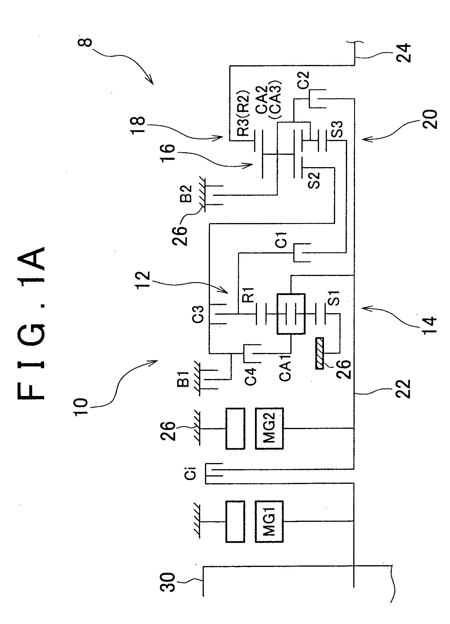
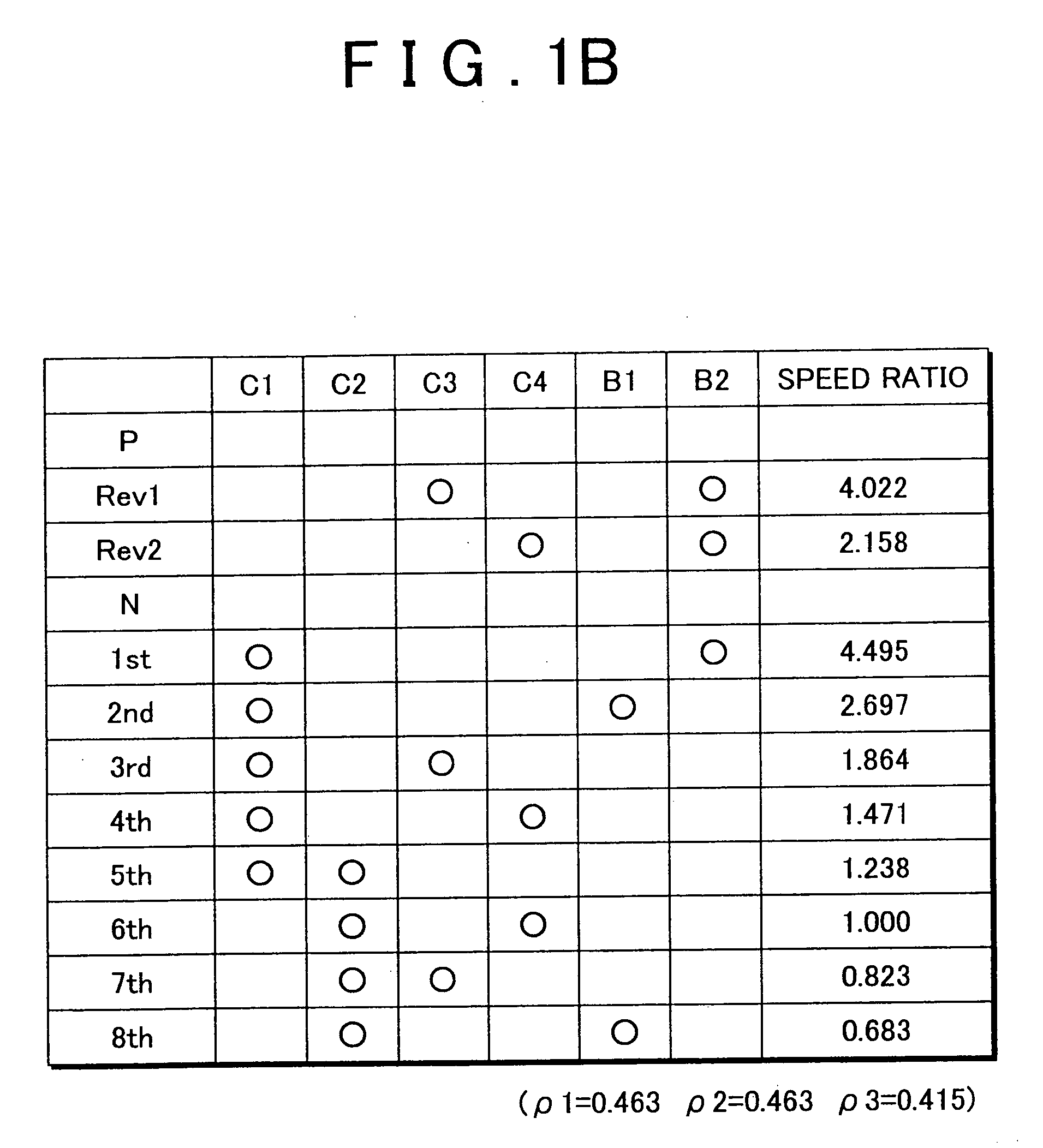
[0073] Hereinafter, exemplary embodiments of the invention will be described in detail with reference to the accompanying drawings. FIG. 1A is a skeleton graph of a drive system 8 for a hybrid vehicle to which the invention is applied. FIG. 1B is a clutch and brake application chart showing various application and release combinations of clutches and brakes to achieve a plurality of speeds in an automatic transmission 10 provided in the drive system 8. The vehicle drive system 8 includes an engine 30 which generates power by burning fuel, a first electric motor MG1, a second electric motor MG2, and an automatic transmission 10, all arranged along the same axis in that order. This vehicle drive system 8 is preferably used in an FR vehicle in which the engine is longitudinal mounted (i.e., mounted in the longitudinal direction of the vehicle). The engine 30 and the second electric motor MG2 are mainly used as the power sources for running, while the first electric motor MG1 is mainly ...


PUM


Abstract

A target deceleration of a vehicle is increased or decreased under given conditions and braking force is controlled in accordance with the increased or decreased target deceleration. Upon the increase or decrease in the target deceleration, the rate of change in the target deceleration is variably set.

Description

BACKGROUND OF THE INVENTION INCORPORATION BY REFERENCE [0001] The disclosure of Japanese Patent Application No. 2004-274145 filed on Sep. 21, 2004 including the specification, drawings and abstract is incorporated herein by reference in its entirety. [0002] 1. Field of the Invention [0003] The invention relates to deceleration control apparatus and method for a vehicle, and more particularly, to deceleration control apparatus and method that enable increases and decreases in a target deceleration to be set appropriately. [0004] 2. Description of the Related Art [0005] A deceleration control apparatus for a vehicle has been proposed which has target deceleration controlling means for increasing and decreasing a target deceleration, and which controls a braking force in accordance with the target deceleration set by that target deceleration controlling means. The apparatus disclosed in JP(A) 2000-245016 is one example of such a deceleration control apparatus. This apparatus is provide...

Claims


Application Information

Patent Timeline
IPC IPC(8): B60K6/00B60L15/20B60T7/12
CPCB60K6/442Y02T10/7258B60L7/26B60L11/123B60L11/14B60L2240/24B60L2250/24B60L2250/26B60W10/08B60W10/10B60W20/00B60W2720/106F16H2200/006F16H2200/0086F16H2200/2007F16H2200/2023F16H2200/2097Y02T10/6217Y02T10/6234Y02T10/7077B60L7/18B60L50/61B60L50/16Y02T10/62Y02T10/7072Y02T10/72Y02T10/70B60W2540/18B60W20/30B60W2552/15
Inventor TABATA, ATSUSHINOZAKI, KAZUTOSHI
Owner TOYOTA JIDOSHA KK
Why Eureka
Try Eureka