Jacketed pipe flange and method

a flange and pipe technology, applied in the direction of flanged joints, pipe joints, fluid pressure sealing joints, etc., can solve the problems of system inability to determine if the problem is a core pipe fracture, reduce flow rate, and increase heat loss, so as to avoid the risk of jumper lines around the flange, avoid high flow rate, overcome the effect of misalignment of the flang

Inactive Publication Date: 2006-03-23
WILKINSON III JOSEPH
View PDF2 Cites 14 Cited by
  • Summary
  • Abstract
  • Description
  • Claims
  • Application Information

AI Technical Summary

Benefits of technology

[0008] A significant feature of the jacketed pipe flange is that the risks associated with the jumper line around the flange are avoided. High flow rates are maintained through the mating flanges, and misalignment of mating flanges is overcome. A related feature of the invention is that various sensors and detectors may be used for accurately detecting the precise location of a leak past the first sealing surface which seals fluid within the inner pipe.

Problems solved by technology

This jumper line creates significant problems, including loss of heat at the flanges, significantly reduced flow rates through the shell pipe, exposure to damage, and insulation sealing of the shell pipe and the jumper which commonly results in separation and disrepair, causing additional loss of heat.
When a core pipe leak is detected in a particular section of piping, the system cannot determine if the problem is a core pipe fracture or a internal gasket leak.

Method used


Image

  • Jacketed pipe flange and method
  • Jacketed pipe flange and method
  • Jacketed pipe flange and method

Examples


Embodiment Construction

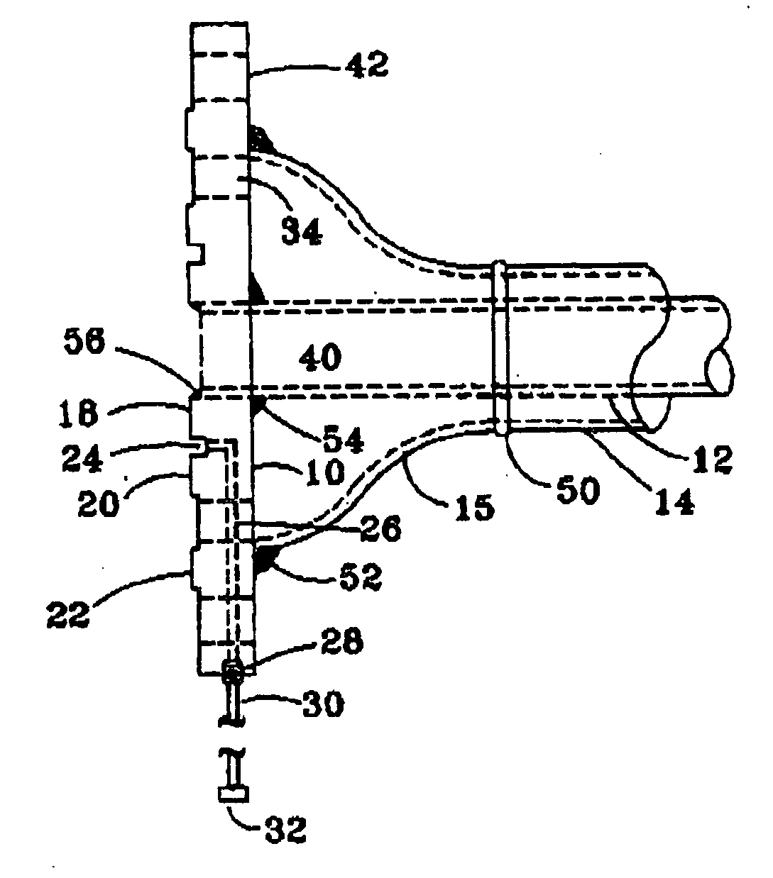
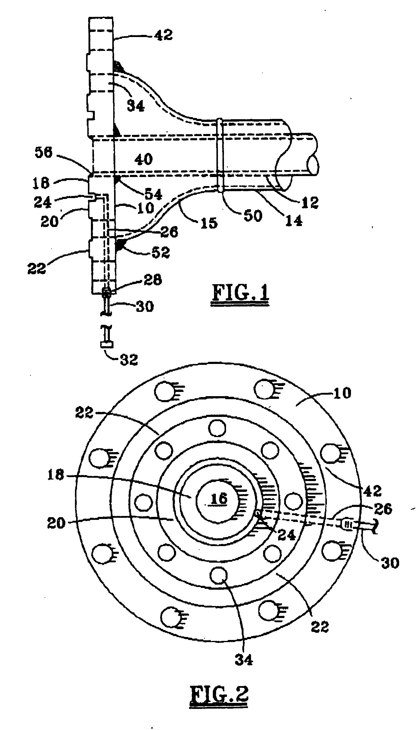
[0013]FIG. 1 illustrates one embodiment of a pipe flange 10 according to the present invention for passing fluid from an inner pipe 12 to the continuation of the pipe 12 secured to a mating flange, and similarly for passing fluid in the annulus between the inner pipe 12 and the outer pipe 14 to the annulus to a continuation of pipes 12 and 14 secured to a mating flange. The outer pipe 14 is connected to the bell portion 15 at annular weld 50, and is welded to the flange 10 at annular weld 52. The inner pipe 12 may be similarly welded to the flange 10 at welds 54 and 56.

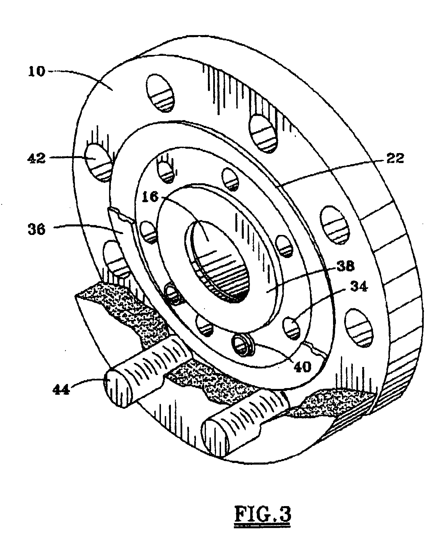
[0014] The flange 10 includes a central throughport 16 for mating with an end of the inner pipe 12 to pass fluid from the inner pipe 12 through the port 16 in the flange 10. An annular sealing surface 18 surrounds the central throughport 16 for sealing fluid within the inner pipe 12. A second annular sealing surface 20 surrounds the first annular sealing surface 18, with an annular gap 24 separating the first and sec...


PUM


Abstract

A jacketed pipe flange 10 for connection to an end of an inner pipe 12 and to an end of a jacketed outer pipe 14 surrounding the inner pipe includes a central throughport 16 for mating with the inner pipe. The first annular sealing surface 18 surrounds a central throughport for sealing fluid within the inner pipe, a second annular sealing surface 20 surrounds the first sealing surface, and a third annular sealing surface 22 surrounds the second annular sealing surface for sealing fluid in the jacketed outer pipe from the exterior of the flange. An annular gap 24 separates the first and second sealing surfaces, and a test port 26 fluidly connects the annular gap with an exterior port in the flange. A plurality of axially extending throughports 34 in the flange between the second and third sealing surfaces pass fluid through the jacketed outer pipe and the flange to downstream components.

Description

FIELD OF THE INVENTION [0001] The present invention relates to a jacketed pipe flange of the type useful for connecting to an inner pipe and a jacketed outer pipe surrounding the inner pipe. More particularly, the jacketed pipe flange includes a plurality of sealing surfaces and the plurality of throughports between the intermediate and the outer sealing surfaces for passing fluid through the jacketed outer pipe. BACKGROUND OF THE INVENTION [0002] The jacketed pipe is commonly used in the petrochemical and hydrocarbon refining industry. The inner pipe is surrounded by the outer pipe, thereby creating two separate flow compartments. The inner pipe, which is also referred to as the core pipe, is commonly used to transfer a product, while the outer pipe, commonly referred to as a shell, transfers a heating media, such as condensate, steam, or other products which transfer heat to the product in the core pipe. [0003] With a traditional design of a jacketed pipe, the heating media bypass...

Claims


Application Information

Patent Timeline
Patent Type & Authority Applications(United States)
IPC IPC(8): F16L23/00
CPCF16L23/032F16L2201/30F16L39/005F16L23/16F16L23/167
Inventor WILKINSON, JOSEPH III
Owner WILKINSON III JOSEPH
Why Eureka
Try Eureka