Prisoner seat security device

a security device and seat technology, applied in the field of prisoner seats, can solve the problems of preventing the ability of officers to assault officers or operate police vehicles, and achieve the effects of low profile, increased vehicle resale value, and low profile design

Inactive Publication Date: 2006-03-23
SQUIRES KEITH D +1
View PDF13 Cites 8 Cited by
  • Summary
  • Abstract
  • Description
  • Claims
  • Application Information

AI Technical Summary

Benefits of technology

[0009] It causes minimal damage to a vehicle as a result of installation, and thus increases the vehicle resale value.
[0010] It can be easily moved from one vehicle and reinstalled into another.
[0011] It has a low profile design which allows the seat to still be utilized for non-prisoner passengers.
[0012] The low profile design and simplicity of use are less likely to create anxiety by the prisoner.

Problems solved by technology

This prevents their ability to assault the officer or operate the police vehicle.

Method used


Image

  • Prisoner seat security device
  • Prisoner seat security device
  • Prisoner seat security device

Examples


Embodiment Construction

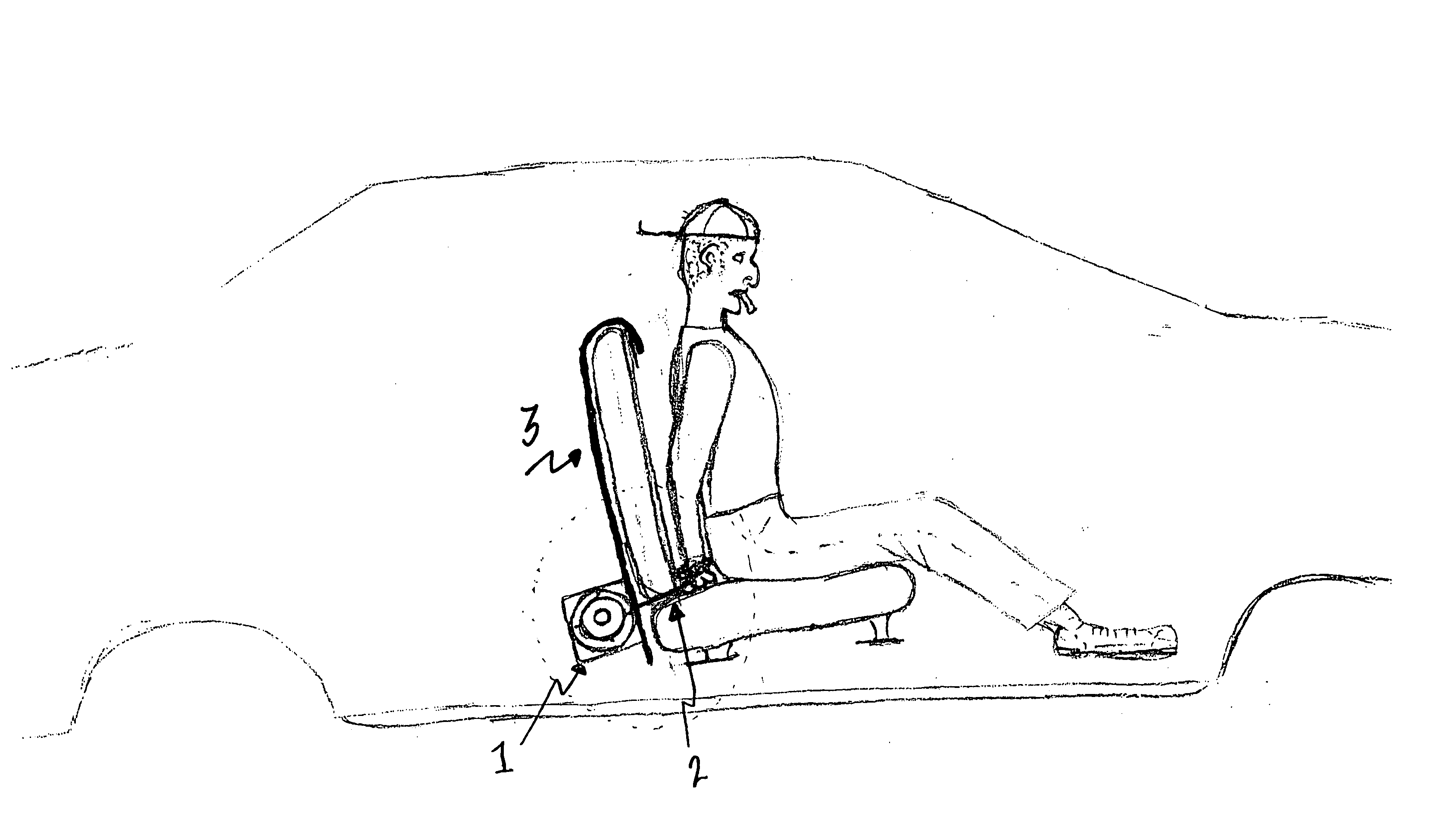
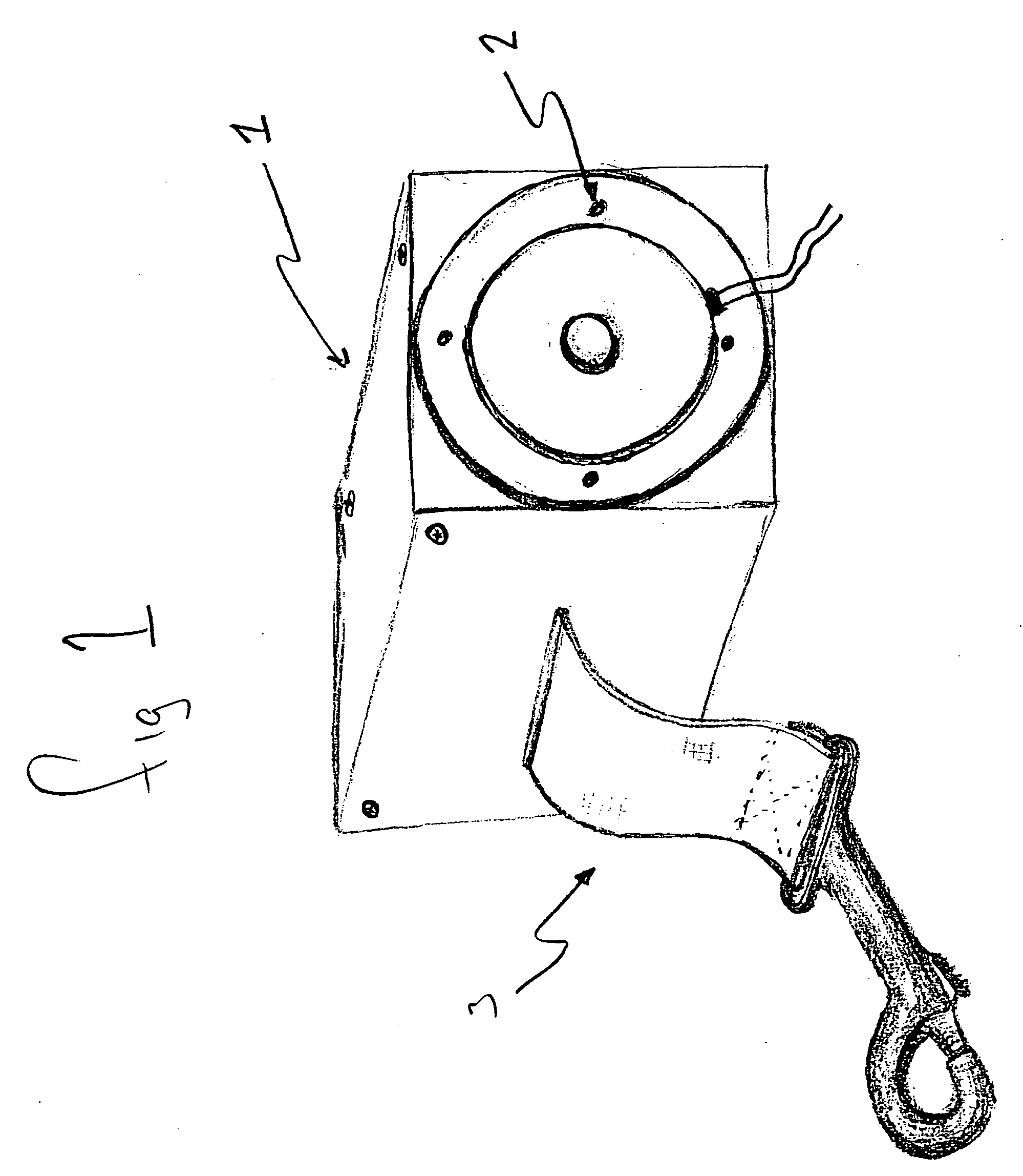
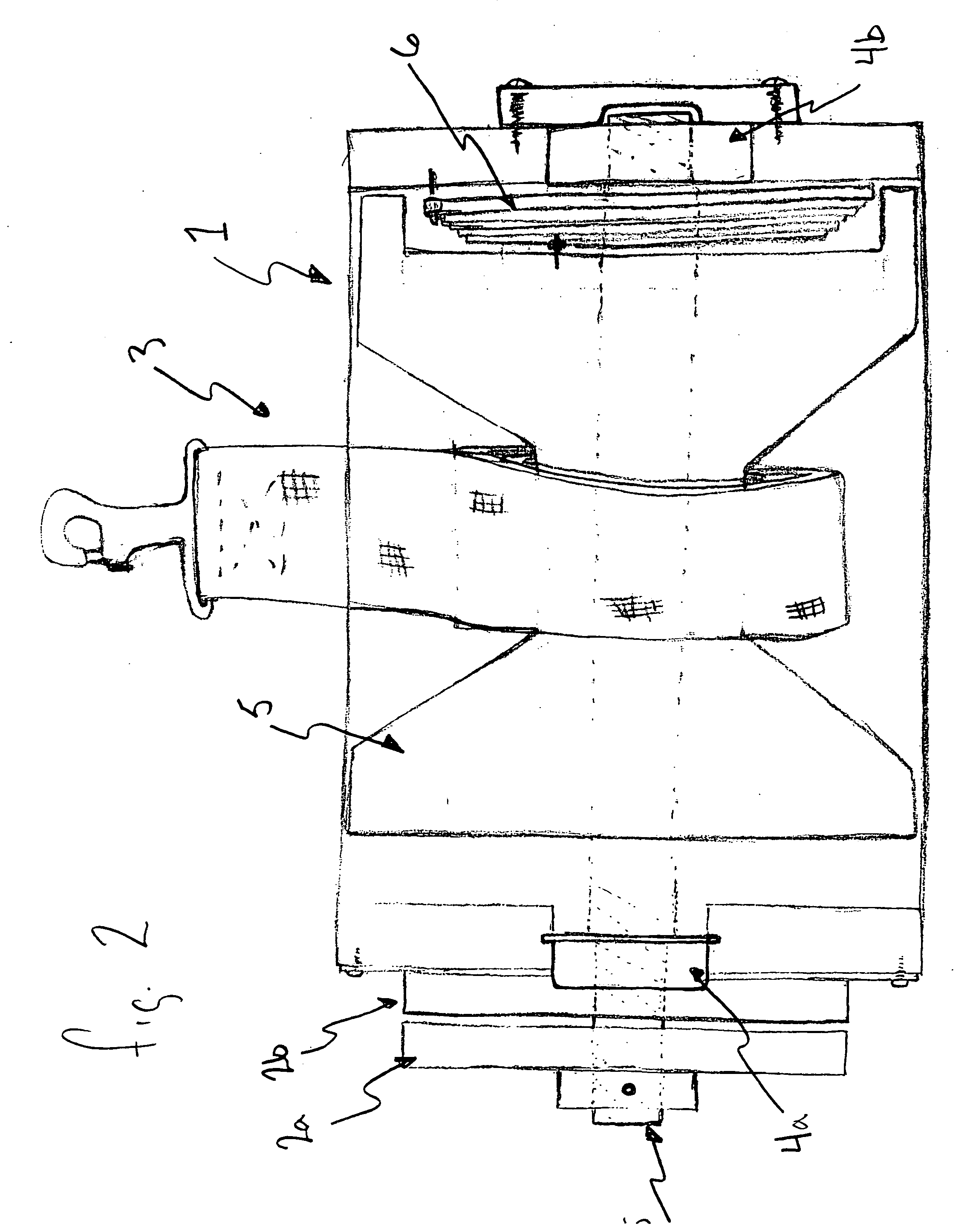
[0022] The retractable restraint device as shown in FIG. 2 consists of a case assembly (FIG. 2(1)); electromagnetic brake (FIG. 2(2a, b)); strap assembly (FIG. 2(3)); sealed bearing assemblies (FIG. 2(4a, b)); shaft and spool assembly (FIG. 2(5)); return spring (FIG. 2(6)); and restraint strap (FIG. 2(3)).

[0023] The free end of the restraint strap (FIG. 2(3)) is allowed to pass from the case assembly (FIG. 2(1)) through an opening cut into the case assembly (FIG. 2(1)). The free end of the restraint strap (FIG. 2(3)) is intended to have a clasp or hook to attach to the restrained prisoner's handcuffs.

[0024] The restraint strap (FIG. 2(3)) is wound on the shaft and spool assembly (FIG. 2(5)) which is kept in a state of tension by return spring (FIG. 2(6)). This provides for the retraction of the restraint strap (FIG. 2(3)) when the invention is in the inactive mode. The shaft and spool assembly rides on the two bearing assemblies (FIG. 2(4a, b)) to allow free movement of the shaft ...


PUM

PropertyMeasurementUnit
currentaaaaaaaaaa
forceaaaaaaaaaa
voltageaaaaaaaaaa

Abstract

A device to restrain a prisoner has a nylon strap attached to a spring-loaded spool, which the operator attaches by means of a clasp to the prisoner's handcuffs or restraining apparatus, and the nylon strap automatically retracts through the seat into the spool's housing located behind the seat as the prisoner sits down. When the prisoner is seated against the seatback, the law enforcement officer activates a remote-control locking switch, which causes a 12-volt braking mechanism to engage and prevent the nylon strap from being pulled out, which holds the prisoner securely in place against the seat and prevents him/her from being able to move enough to release a seatbelt or unlock and open a vehicle door. When the officer is ready to remove the prisoner, he/she again activates the remote-controlled switch which releases the brake and allows the nylon strap to be extracted while the prisoner steps away from the seat.

Description

BACKGROUND OF THE INVENTION [0001] Law enforcement, corrections, security and military personnel transport handcuffed or otherwise fettered prisoners in various vehicles from one location to another. Traditionally, a police officer arrests a suspect and places him / her into handcuffs. The prisoner is then placed in the police vehicle, which is often equipped with an aftermarket cage that prevents the suspect from exiting the back seat compartment. The cage requires hard installation to the vehicle and prevents the rear passenger compartment from being utilized for other purposes. Many officers and departments forego the use of a cage and place the handcuffed prisoner in the front passenger seat and then only use a seatbelt to them. This practice can allow intent prisoners to move around freely enough to unlatch the seatbelt, unlock and open the vehicle's door to escape, and in some circumstances to move the handcuffs from behind the back to the front, which facilitates a possible ass...

Claims


Application Information

Patent Timeline
Patent Type & Authority Applications(United States)
IPC IPC(8): A47D15/00
CPCA47C7/62Y10T29/49904Y10T29/49826E05B75/00Y10T70/404
Inventor SQUIRES, KEITH D.ISSA, OMAR L.
Owner SQUIRES KEITH D
Why Eureka
Try Eureka