Uniformity and brightness measurement in OLED displays

a technology of uniformity and brightness, applied in the field of system and method for measuring the performance of oled displays, can solve the problems of limiting the quality of oled displays, oled displays suffering from non-uniformity of light-emitting elements, and no specification for the resolution of imaging systems or analysis processes, so as to achieve the effect of improving efficiency and accuracy

Inactive Publication Date: 2006-03-23
EASTMAN KODAK CO
View PDF6 Cites 85 Cited by
  • Summary
  • Abstract
  • Description
  • Claims
  • Application Information

AI Technical Summary

Benefits of technology

[0011] The present invention has the advantage of providing improved efficiency and accuracy in measuring the uniformity of an OLED display.

Problems solved by technology

However, such displays suffer from a variety of defects that limit the quality of the displays.
In particular, OLED displays suffer from non-uniformities in the light-emitting elements.
These non-uniformities can be attributed to both the light-emitting materials in the display and, for active-matrix displays, to variability in the thin-film transistors used to drive the light-emitting elements.
However, no specification for the resolution of the imaging system or the analysis process is provided.
Such a process is time-consuming and requires mechanical fixtures to acquire the plurality of sub-area images.
However, this technique is very inefficient and slow in a realistic manufacturing environment.
However, digital cameras typically have a limited exposure range and bit depth within which the imaging devices can capture a scene.
The imaging devices also have a limited number of bits limiting the number of light levels that can be distinguished by the imaging device.
Hence, for scenes that have a wide brightness range, i.e. both very bright and very dim portions, a single image captured by the imaging device cannot distinguish between light levels that are relatively much closer together where the differences in light levels are below a threshold value.
However, such non-uniformities may be readily perceptible to a user, particularly at lower light levels.
However, applicants have determined that the presence of non-uniformities in an OLED display is at least partially dependent on the brightness of the display.
Hence, limiting the brightness of the display may overlook non-uniformities that occur at brighter display levels.

Method used


Image

  • Uniformity and brightness measurement in OLED displays
  • Uniformity and brightness measurement in OLED displays
  • Uniformity and brightness measurement in OLED displays

Examples


Embodiment Construction

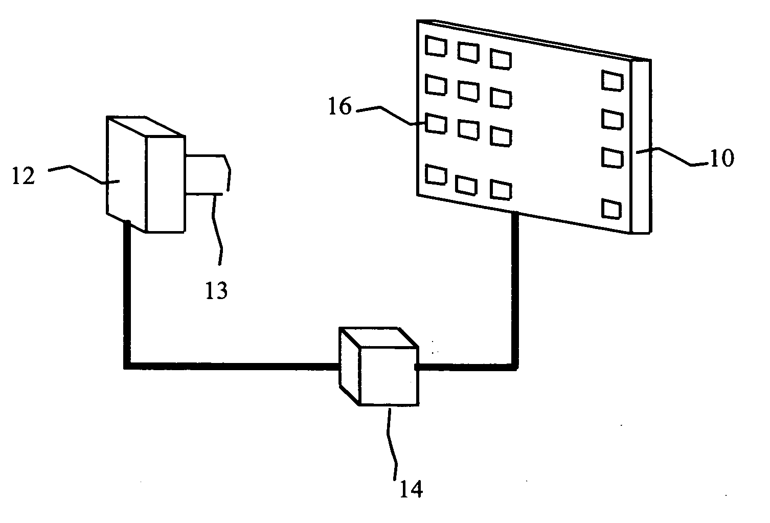
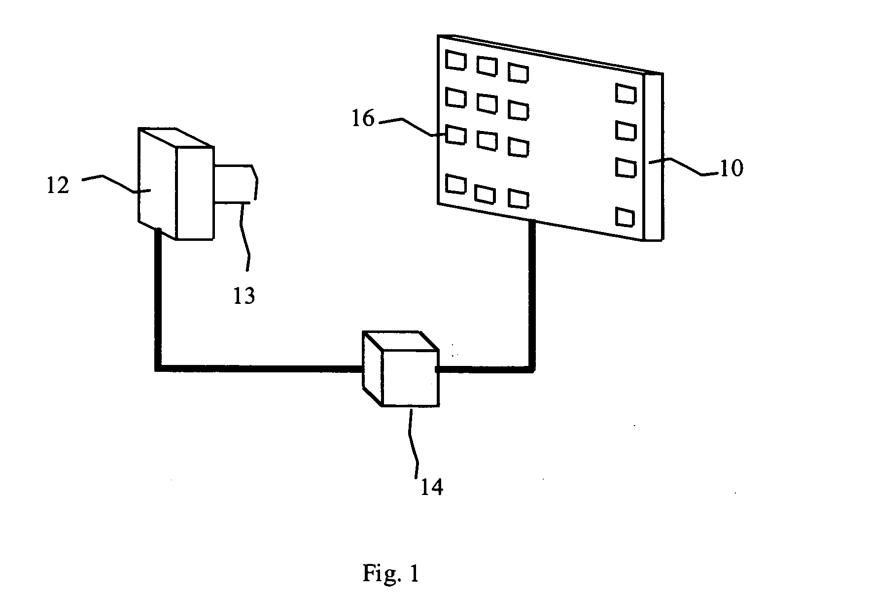
[0017]FIG. 1 depicts a system for the detection of brightness uniformity variations in light-emitting elements in an OLED display 10 having a plurality of light-emitting elements 16 having perceptible brightness uniformity variations less than a threshold value when driven with a common signal; an imager 12 with one or more light-sensitive sensor elements having variable light exposure levels and sensitive to the light emitted by the light-emitting elements, where the sensor elements are not capable of detecting brightness uniformity variations less than the threshold value at a first light exposure level; optical elements 13 arranged so that the light-sensitive sensor elements are exposed to the light-emitting elements of the OLED display; and a controller 14 programmed to control the OLED display and cause the light-emitting elements to illuminate and the imager to acquire images of the illuminated light-emitting elements in the OLED display at at least the first and a different s...


PUM


Abstract

A system for the detection of brightness uniformity variations in light-emitting elements in an OLED display is described, comprising: a) an OLED display having a plurality of light-emitting elements having perceptible brightness uniformity variations less than a threshold value when driven with a common signal; b) an imager with one or more light-sensitive sensor elements having variable light exposure levels and sensitive to the light emitted by the light-emitting elements, where the sensor elements are not capable of detecting brightness uniformity variations less than the threshold value at a first light exposure level; c) optical elements arranged so that the light-sensitive sensor elements are exposed to the light-emitting elements of the OLED display; and d) a controller programmed to control the OLED display and cause the light-emitting elements to illuminate and the imager to acquire images of the illuminated light-emitting elements in the OLED display at at least the first and a different second light exposure level.

Description

FIELD OF THE INVENTION [0001] The present invention relates to systems and methods for measuring performance of OLED displays having a plurality of light-emitting elements. BACKGROUND OF THE INVENTION [0002] Organic Light Emitting Diodes (OLEDs) have been known for some years and have been recently used in commercial display devices. Such devices employ both active-matrix and passive-matrix control schemes and can employ a plurality of light-emitting elements. The light-emitting elements are typically rectangular and arranged in two-dimensional arrays with a row and a column address for each light-emitting element and having a data value associated with the light-emitting element value. However, such displays suffer from a variety of defects that limit the quality of the displays. In particular, OLED displays suffer from non-uniformities in the light-emitting elements. These non-uniformities can be attributed to both the light-emitting materials in the display and, for active-matrix...

Claims


Application Information

Patent Timeline
Patent Type & Authority Applications(United States)
IPC IPC(8): H05B33/00
CPCG09G3/3208G09G2320/043H04N17/04G09G2360/145G09G2320/0693
Inventor COK, RONALD S.FORD, JAMES H.
Owner EASTMAN KODAK CO
Why Eureka
Try Eureka