

Antenna apparatus
- Summary
- Abstract
- Description
- Claims
- Application Information
AI Technical Summary
Benefits of technology
Problems solved by technology
Method used
Image

Examples
first embodiment
The First Embodiment
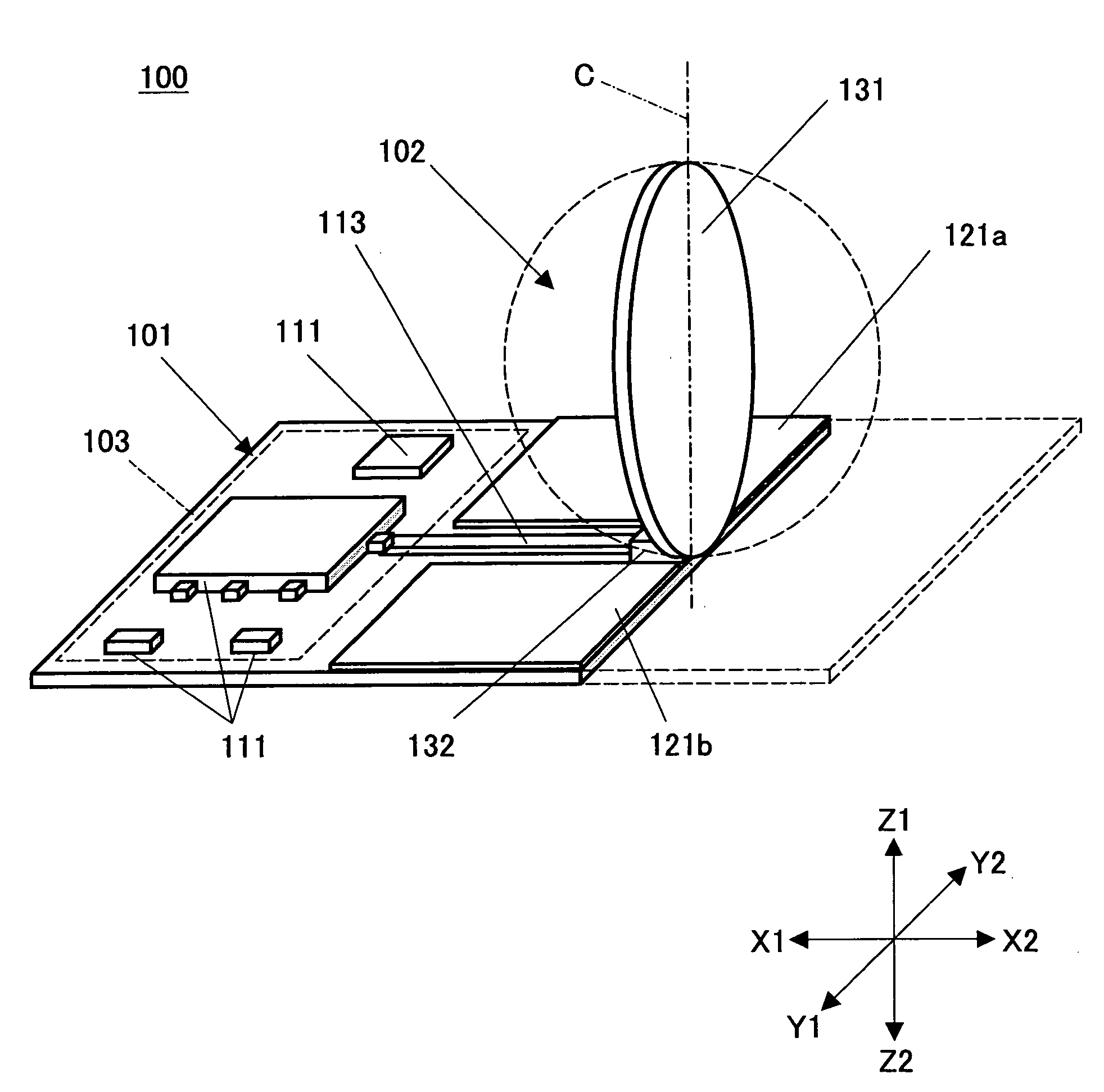
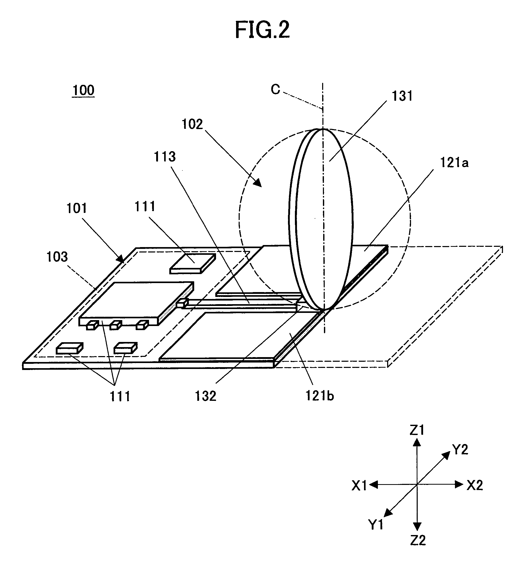
[0041]FIG. 2 is a perspective diagram of an antenna apparatus 100 according to the first embodiment of the present invention, and FIG. 3 is an orthographic projection thereof.
[0042] The antenna apparatus 100 of the present embodiment includes a printed wiring board 101, an antenna unit 102, and an RF circuit unit 103.
[0043] The printed wiring board 101 is made from dielectrics such as resin and ceramics, for example, FR-4, and CEM3, on the surface of which electronic parts 111 are mounted. The electronic parts 111 mounted on the printed wiring board 101 are connected by an electrically conductive pattern 112 (illustration omitted), and constitute the RF circuit unit 103. The RF circuit unit 103 is connected to the antenna unit 102 by a microstrip line 113 formed on the printed wiring board 101.
[0044] The antenna unit 102 includes a ground plate 121 and the feeding unit 122.
[0045] The ground plate 121 is constituted by electrically conductive patterns 121a and...
second embodiment
The Second Embodiment
[0053]FIG. 4 is a perspective diagram of an antenna apparatus 200 according to the second embodiment of the present invention, and FIG. 5 is an orthographic projection thereof. The same reference numbers are given to the components the same as FIG. 2 and FIG. 3, and the explanation thereof is not repeated.
[0054] The antenna apparatus 200 includes an antenna unit 202 that is different from the antenna unit 102 of the first embodiment. The antenna unit 202 of the second embodiment includes a feeding unit 222 that is different from the feeding unit 122 of the first embodiment.
[0055] The feeding unit 222 of the second embodiment includes a feeding plate 231 that is made into the form where the plane form of the feeding plate 131 (of the first embodiment) is cut at about one-half height H / 2.
[0056] Since the height of the feeding plate 231 is about a half of the first embodiment, the feeding unit 202, and therefore the antenna apparatus 200, can be made even thinne...
third embodiment
The Third Embodiment
[0057]FIG. 6 is a perspective diagram of an antenna apparatus 300 according to the third embodiment of the present invention, and FIG. 7 is an orthographic projection thereof. The same reference numbers are given to the components the same as FIG. 4 and FIG. 5, and the explanation thereof is not repeated.
[0058] The antenna apparatus 300 of this embodiment includes an antenna unit 302 that is different from antenna unit 202 of the second embodiment. Further, the antenna unit 302 of this embodiment includes a feeding unit 322 that is different from the feeding unit 222 of the second embodiment.
[0059] The feeding unit 322 of this embodiment include a feeding plate 331 that is arranged not perpendicular to the printed wiring board 101, but at an angle φ.
[0060] In other words, the feeding plate 331 is arranged inclining to the fixing part 132 at the angle φ.
[0061] According to this embodiment, the height H2 of the antenna apparatus 300 is lower than the height of ...
PUM
 Abstract
Description
Claims
Application Information