Method for controlling computer system having wireless display and computer system

a computer system and wireless display technology, applied in the direction of instruments, liquid/fluent solid measurement, electrical apparatus casings/cabinets/drawers, etc., can solve the problems of data loss, computer system termination in abnormal state, cumbersome tasks,

Inactive Publication Date: 2006-03-23
FUJITSU LTD
View PDF3 Cites 36 Cited by
  • Summary
  • Abstract
  • Description
  • Claims
  • Application Information

AI Technical Summary

Benefits of technology

[0007] An object of the present invention is to prevent a computer system including a wireless display from bein

Problems solved by technology

Under such circumstances, another person may misunderstand that the computer main unit is not used although its power is turned on, and he or she may turn off the power of the computer main unit.
In this case, an application in service

Method used


Image

  • Method for controlling computer system having wireless display and computer system
  • Method for controlling computer system having wireless display and computer system
  • Method for controlling computer system having wireless display and computer system

Examples


first embodiment

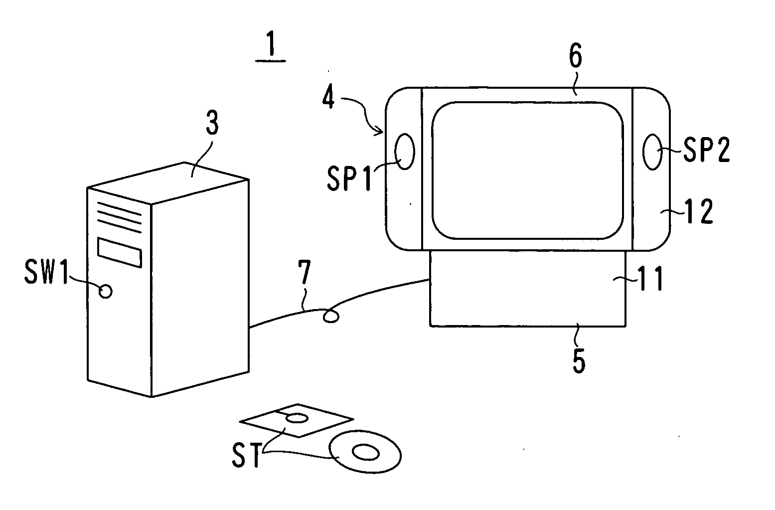
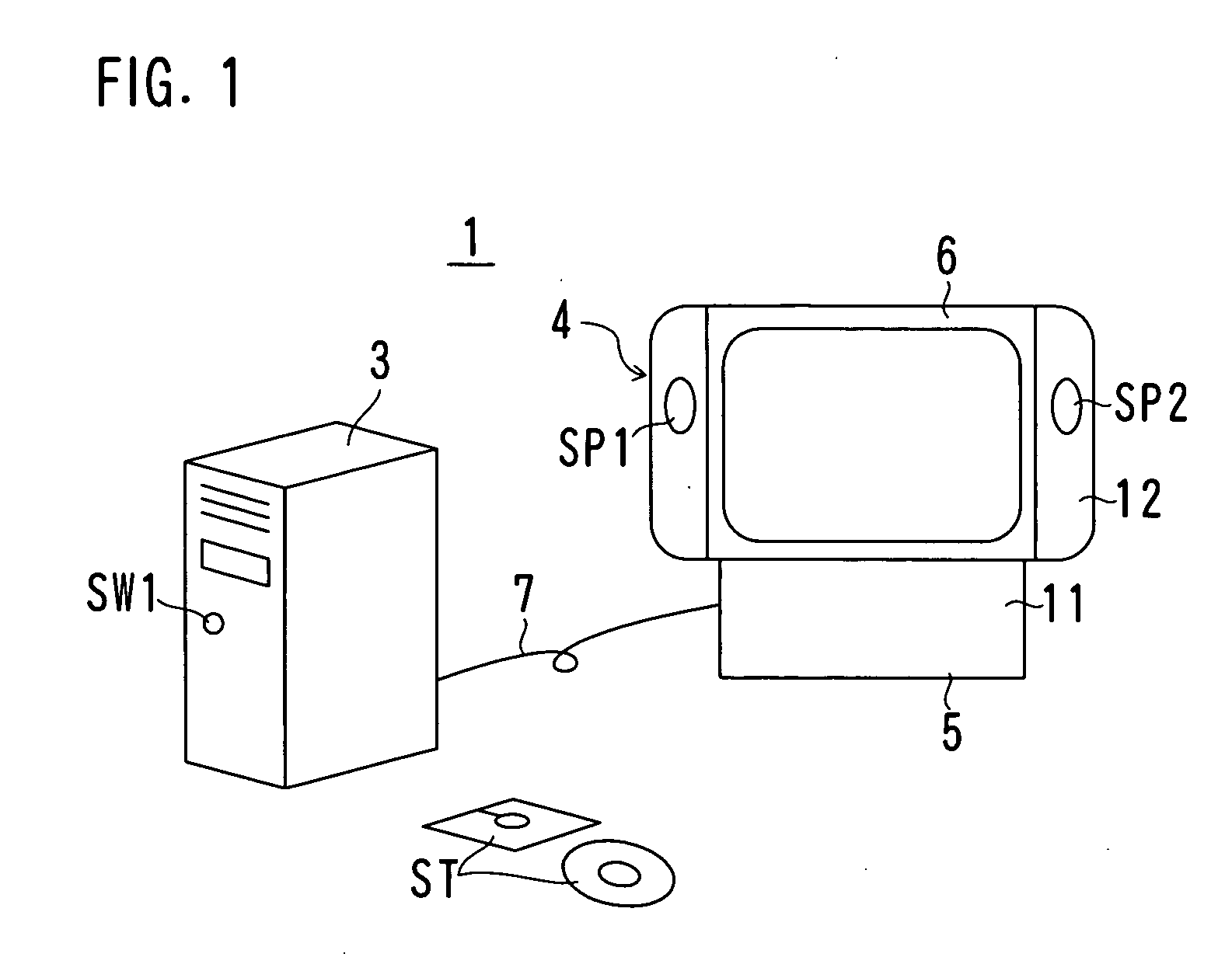
[0011] As shown in FIG. 1, a computer system 1 includes a computer main unit 3, a display device 4 and a cable 7 for connecting them to each other.

[0012] The computer main unit 3 includes a CPU, a RAM, a ROM, other peripheral elements, various interfaces, a hard disk drive and a magneto-optical disk drive. Various application programs are executed on an operating system (OS) so that various kinds of data processing are performed. Data are read or written on various recording media ST such as a CD-ROM or a flexible disk. A power plug is connected to a power source line to be supplied with AC power. A power switch SW1 is provided, and power is turned on or off or reset by operating the power switch SW1. However, the computer system 1 of this embodiment can ignore the operation of the power switch SW1 depending on a connected or detached state of the display device 4. Detail will be described later. In addition, a printer, a mouse, a keyboard and a communication line to a network are ...

second embodiment

[0050] Next, a computer system 1B of a second embodiment will be described.

[0051] The computer system 1B of the second embodiment is different from the computer system 1 of the first embodiment in the method of detecting the connected or detached state of the display 6 and the method of transmitting the detection signal S2 to the computer main unit 3, while other structures are the same between them. Therefore, the same reference signs are used for parts having the same functions as the computer system 1 of the first embodiment so as to omit or simplify descriptions.

[0052] In the second embodiment, a display driver that is software for controlling the display device 4 enables to detect the connected or detached state of the display 6. In other words, the display driver for controlling the display device 4 should be installed in the computer main unit 3, and a program for detecting the connected or detached state of the display 6 is incorporated in the display driver. Such a progra...


PUM


Abstract

A system includes a computer main unit (3) for performing data processing, a cradle (5) for a display device that is connected to the computer main unit so that signals or data can be communicated between them, a wireless display (6) that is detachably connected to the cradle and is capable of communicating signals or data with the cradle or the computer main unit via wireless communication, a connector, a resistor or the like as a detecting portion for detecting a connected or detached state of the wireless display with respect to the cradle, and a NOR circuit (35) or a power control portion (33, 33B) as a control portion for inhibiting power control by an operation in the computer main unit when the wireless display is detached from the cradle and the computer main unit is working.

Description

TECHNICAL FIELD [0001] The present invention relates to a method for controlling a computer system having a wireless display and a computer system. In particular, the present invention is used for controlling power supply to a computer system in which a wireless display can be switched between a wired operation and a wireless operation. BACKGROUND ART [0002] Presently, there is provided a computer system that allows its display to be separated and carried for use to any place such as a living room or a kitchen in a house. In this computer system, a computer main unit and a display are connected to each other via a wireless network. [0003] The display (wireless display) employs a flat display panel such as a liquid crystal display device that works on a secondary battery as its power source, and it is adapted to be compact and lightweight so as to be capable of being carried independently. The display has a function of processing as a computer as well as a function of wireless commun...

Claims


Application Information

Patent Timeline
IPC IPC(8): G06F1/16G06F1/26G06F1/32G06F3/02
CPCG06F1/1601G06F1/1626G06F2200/1631G06F1/3215G06F3/0227G06F1/1632
Inventor HARA, TAKUYA
Owner FUJITSU LTD
Why Eureka
Try Eureka