
Apparatus of making wedged plates

a wedged plate and wedge technology, applied in the field of wedged plate apparatus, can solve the problems of unstable optical properties of plates made by injection molding, slow injection molding mass production, and uneven thickness of plates, and achieve the effect of fast mass production

Inactive Publication Date: 2006-03-23
FRANCIS CHUNG HWA PAN
View PDF2 Cites 23 Cited by
  • Summary
  • Abstract
  • Description
  • Claims
  • Application Information

AI Technical Summary

Benefits of technology

[0006] The primary objective of the present invention is to provide an apparatus for making wedged plates, which is fast for mass production and has no residue stress in the plate.

Problems solved by technology

Injection molding is too slow for mass production because only one plate is molded in each process.
While molding the large plate by injection molding, the plate might warp.
In addition, the plate made by injection molding usually has unstable optical properties because there is residue stress in the plate.

Method used


Image

  • Apparatus of making wedged plates
  • Apparatus of making wedged plates
  • Apparatus of making wedged plates

Examples


Embodiment Construction

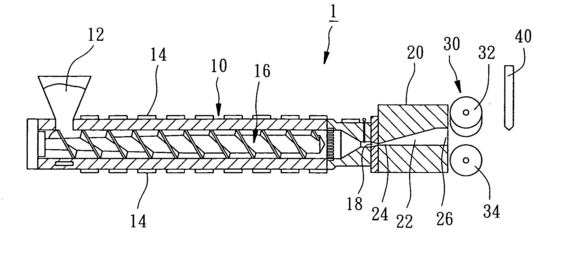
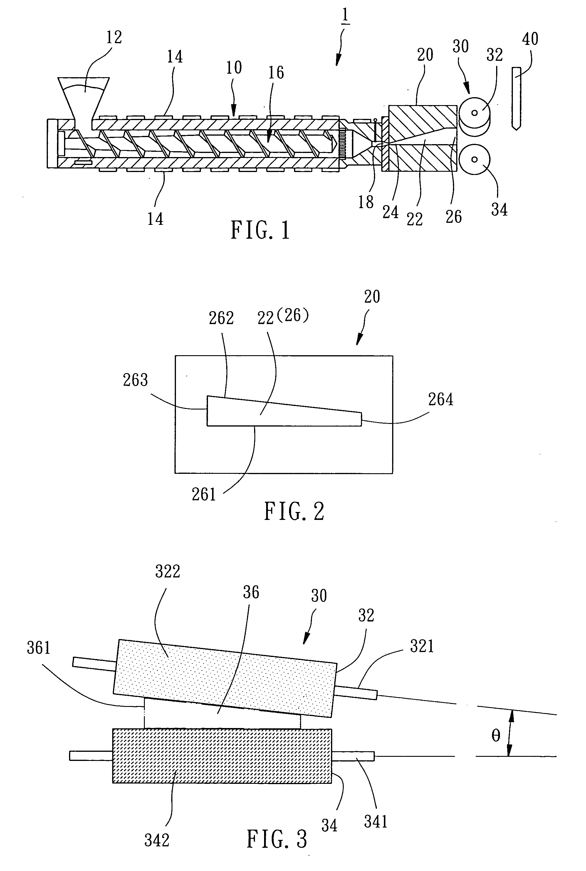
[0023] As shown in FIG. 1, an apparatus 1 for making wedged plates of the first preferred embodiment of the present invention comprises an extruder 10, a die head 20, a rolling device 30 and a cutting device 40.

[0024] The extruder 10 has an inlet 12, a plurality of heaters 14, a screw bar 16 and an outlet 18. Plastic powder or pellets (not shown) is fed to the extruder 10 via the inlet 12, the heaters 14 melt the plastic and the screw bar 16 extrudes the melted plastic out of the extruder 10 via the out let 18.

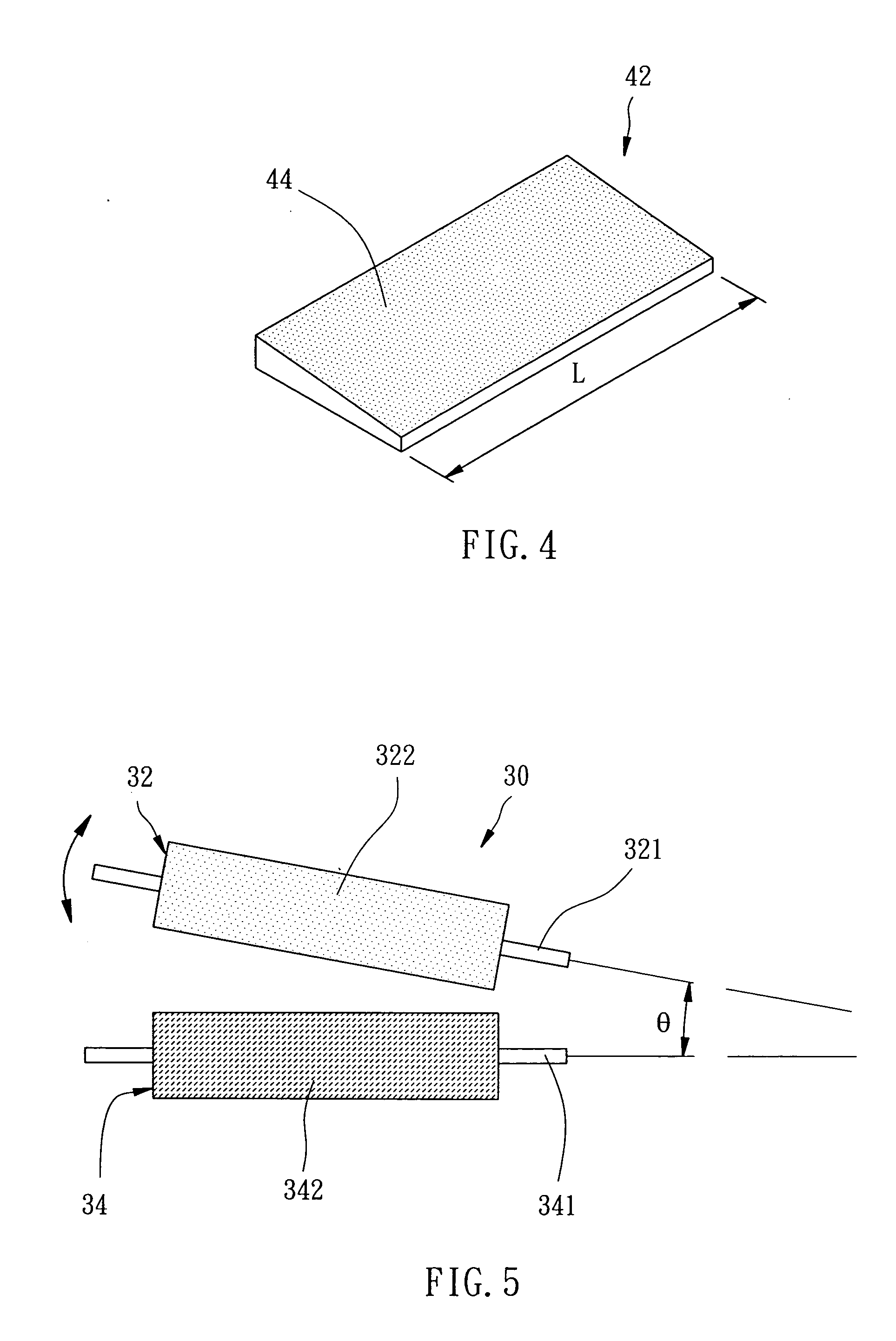
[0025] The die head 20 has a channel 22 therein with an inlet 24 and an outlet at opposite ends thereof. The inlet 24 of the die head 20 is connected to the outlet 18 of the extruder 10, so that the melted plastic can flow into the channel 22 of the die head 20. As shown in FIG. 2, the outlet 26 of the channel 22 has a shape substantially like a wedge, which has a bottom side 261, a top side 262, a first lateral side 263 and a second lateral side 264. A height of the first s...


PUM

PropertyMeasurementUnit
heightaaaaaaaaaa
thickaaaaaaaaaa
included angleaaaaaaaaaa

Abstract

An apparatus for making wedged plate has an extruder to provide melted plastic material. A die head has a channel with an inlet and an outlet. The inlet of the die head is connected to an outlet of the extruder. The outlet of the die head has a thick side and a narrow side. A rolling device has two rollers and a space between the rollers. The space has a thick portion and a narrow portion at opposite sides. The space of the rolling device is aligned with the outlet of the die head, so that the plastic material flows into the space of the rolling device via the die head and is rolled by the rollers. A cutting device is arranged behind the rolling device to cut the rolled plastic material to get wedged plates.

Description

BACKGROUND OF THE INVENTION [0001] 1. Field of the Invention [0002] The present invention relates generally to an apparatus for making plates, and more particularly to an apparatus for making wedged plates. [0003] 2. Description of the Related Art [0004] A conventional liquid crystal display (LCD) has a backlight module, which is typically classified into a direct-lighting backlight module and an edge-lighting backlight module. The edge-lighting backlight module has a light guide plate, which usually is a wedged plate and is made of Polymethyl methacrylate (PMMA), Polycarbonate (PC) Cyclic Olefins Polymer (COP) or Cyclic Olefins Copolymer (COC). [0005] The light guide plate usually is made by injection molding, in which an injector is applied to inject melted plastic into a cavity of a mold. After the plastic has been solidified, the mold is opened to take the plate out. After that, the mold is closed to take next injection process. Injection molding is too slow for mass production ...

Claims


Application Information

Patent Timeline
Patent Type & Authority Applications(United States)
IPC IPC(8): B29C59/00B29C48/07B29C48/12
CPCB29C47/003B29C47/0038B29C47/0066B29C47/14G02B6/0065B29C59/04B29C2793/0063B29L2011/00B29L2031/7738B29C47/32B29C48/12B29C48/001B29C48/0022B29C48/305B29C48/35B29C48/07
Inventor PAN, FRANCIS CHUNG HWAPAN, JOHN CHUNGTEHLEE, CHUN-CHICHEN, CHIH-LUNG
Owner FRANCIS CHUNG HWA PAN
Learn More