
Wireless repeater using cross-polarized signals to reduce feedback in an FDD wireless network

Inactive Publication Date: 2006-03-23
SAMSUNG ELECTRONICS CO LTD
View PDF4 Cites 36 Cited by
  • Summary
  • Abstract
  • Description
  • Claims
  • Application Information

AI Technical Summary

Benefits of technology

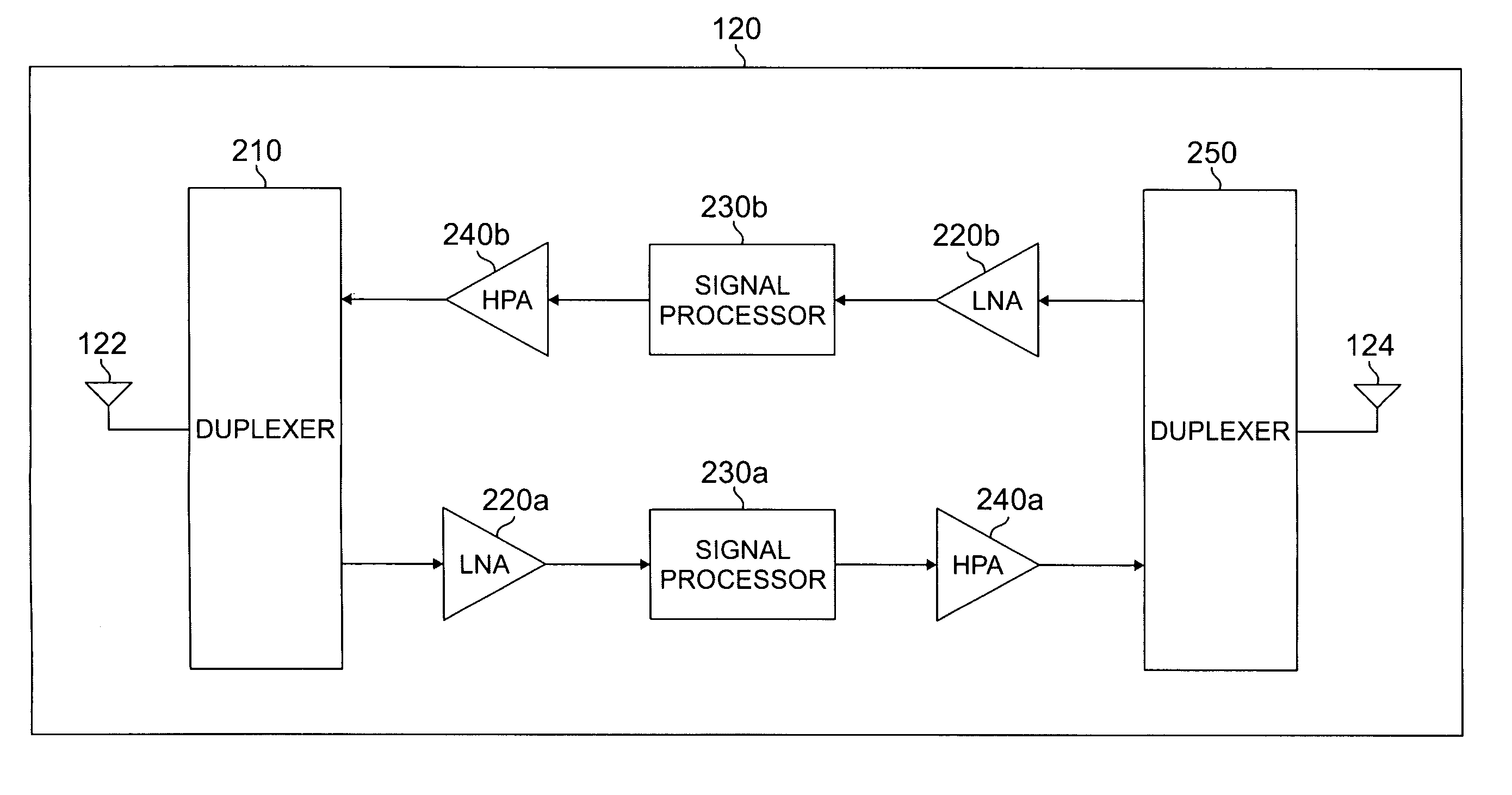
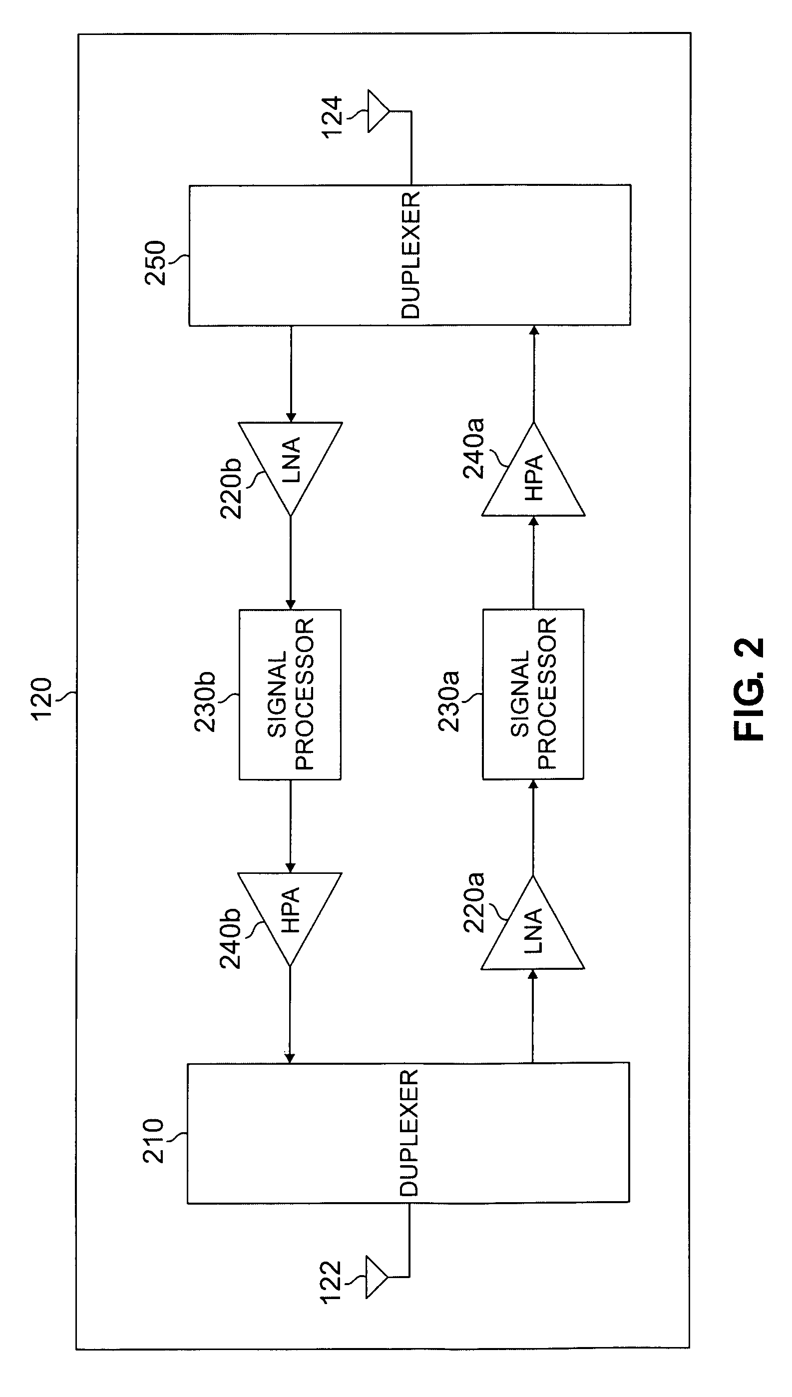
[0012] The present invention provides a wireless repeater for use in a wireless network that employs frequency-division duplexed (FDD) transmission and reception. A repeater according to the principles of the present invention reduces feedback between an output antenna and an input antenna of the repeater that could cause instabilities or oscillations. The present invention uses a combination of antenna cross-polarization techniques and digital processing techniques to remove time-delayed feedback or echo terms. The signal processing techniques described herein may provide another 20-40 dB of gain isolation.
[0014] According to one embodiment of the present invention, a ground plane associated with the repeater is disposed between the first antenna array and the second antenna array to thereby provide isolation between the first and second antenna arrays.
[0016] According to still another embodiment of the present invention, the each echo processor delays transmission of the outgoing one of the forward and reverse channel signals in order to minimize the echo signal in the respective one of the down-converted forward and reverse channel signals.

Problems solved by technology

Inadequate coverage is a persistent problem in the quality of service of any wireless network.
Natural and man-made obstacles frequently create radio frequency (RF) “holes” in the coverage area of a wireless network.
Mobile stations that are already in an RF hole may not be able to reliably establish new connections.
The prior art repeaters generally do not provide a method of canceling any echoes from the output that would lead to unstable operation (i.e., oscillations).

Method used


Image

  • Wireless repeater using cross-polarized signals to reduce feedback in an FDD wireless network
  • Wireless repeater using cross-polarized signals to reduce feedback in an FDD wireless network
  • Wireless repeater using cross-polarized signals to reduce feedback in an FDD wireless network

Examples


Embodiment Construction

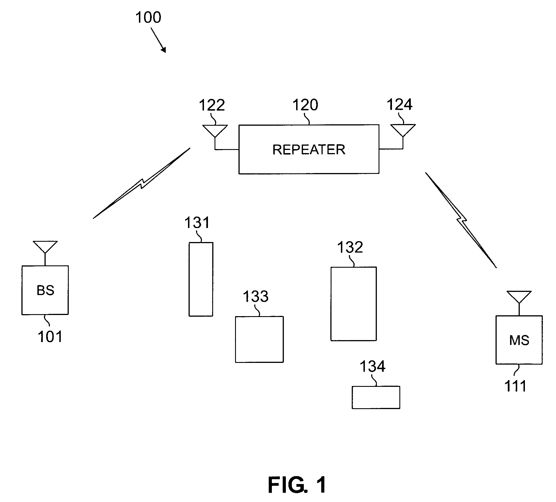
[0031]FIGS. 1 through 6, discussed below, and the various embodiments used to describe the principles of the present invention in this patent document are by way of illustration only and should not be construed in any way to limit the scope of the invention. Those skilled in the art will understand that the principles of the present invention may be implemented in any suitably arranged RF repeater transceiver.

[0032]FIG. 1 illustrates exemplary wireless network 100, which implements repeater 120 according to the principles of the present invention. Wireless network 100 comprises base station (BS) 101 and other base stations (not shown) that communicate with a plurality of mobile stations, such as mobile station (MS) 111, located in a coverage area of wireless network 100. In an advantageous embodiment of the present invention, base station (BS) 101 communicates with mobile station (MS) 111 over frequency-division duplexed (FDD) channels. By way of example, the FDD channels may use c...


PUM


Abstract

A repeater for re-transmitting signals between first and second wireless devices. The repeater comprises a first antenna array for receiving a forward channel signal transmitted from the first wireless device and a second antenna array for receiving a reverse channel signal transmitted from the second wireless device. The repeater also comprises a first transceiver chain for down-converting the received forward channel signal, processing the down-converted forward channel signal, and up-converting the processed forward channel signal to thereby produce an outgoing forward channel signal. The repeater also comprises a second transceiver chain for down-converting the received reverse channel signal, processing the down-converted reverse channel signal, and up-converting the processed reverse channel signal to thereby produce an outgoing reverse channel signal. The first antenna array comprises a first antenna element and the second antenna array comprises a second antenna element that is cross-polarized with respect to the first antenna element.

Description

CROSS-REFERENCE TO RELATED APPLICATIONS AND CLAIM OF PRIORITY [0001] The present invention is related to that disclosed in U.S. Provisional Patent Application Ser. No. 60 / 608,299, filed Sep. 27, 2004, entitled “Method and Procedure for Using a Single RF Chain in a Wireless Repeater For Time-Division Duplexed Signals” and U.S. Provisional Patent Application Ser. No. 60 / 608,282, filed Sep. 27, 2004, entitled “Method and Procedure for Reduction of Feedback in a Wireless Repeater Using Cancellation of Cross-Polarized Signals”. U.S. Provisional Patent Application Ser. Nos. 60 / 608,282 and 60 / 608,299 are assigned to the assignee of the present application. The subject matter disclosed in each of U.S. Provisional Patent Application Ser. Nos. 60 / 608,282 and 60 / 608,299 is hereby incorporated by reference into the present disclosure as if fully set forth herein. The present invention hereby claims priority under 35 U.S.C. §119(e) to U.S. Provisional Patent Application Ser. Nos. 60 / 608,282 and ...

Claims


Application Information

Patent Timeline
IPC IPC(8): H04B7/14
CPCH04B7/15571
Inventor CLEVELAND, JOSEPH R.NELSON, PAUL G.
Owner SAMSUNG ELECTRONICS CO LTD
Learn More